Cooling system of flywheel energy storage device

A technology of heat dissipation system and flywheel energy storage, applied in the field of heat dissipation system of flywheel energy storage device, can solve the problems of cavitation, low pump inlet pressure, inability to work normally, and inability to dissipate heat, and achieve the effect of avoiding cavitation

Active Publication Date: 2015-04-29
ERZHONG DEYANG POWER TECH CO LTD
View PDF5 Cites 30 Cited by
  • Summary
  • Abstract
  • Description
  • Claims
  • Application Information

AI Technical Summary

Problems solved by technology

[0004] The applicant aims at the disadvantages of the above-mentioned existing flywheel accumulators, such as the fact that the heat dissipation of the flywheel accumulator cannot take into account the various components, the inlet pressure of the pump is small and cannot work normally, and it is easy to cause cavitation and cannot dissipate heat, etc., to provide a cooling system for the flywheel accumulator with a reasonable structure, thereby It can not only dissipate heat from key components such as the stator, rotor, and bearings, but also take into account the lubrication of the bearings

Method used


Image

  • Cooling system of flywheel energy storage device
  • Cooling system of flywheel energy storage device
  • Cooling system of flywheel energy storage device

Examples


Embodiment 1

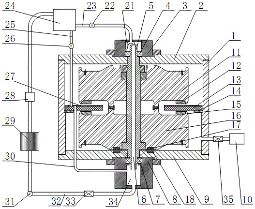
[0029] like figure 1 As shown in the figure, the flywheel energy storage device of the present invention is composed of a casing and an internal disc motor, the rotor of the disc motor and the flywheel are combined into one, and the disc motor can be used as a motor to drive the flywheel to rotate; it can also be used as a generator, which is Flywheel drive to generate electricity. The shell is composed of a cylinder body 1, an upper cover plate 2 and a lower cover plate 9. An upper bearing seat 3 and a lower bearing seat 8 are respectively fixed in the center of the upper cover plate 2 and the lower cover plate 9, and the upper bearing 4 is embedded in the upper bearing seat 3. An upper oil cavity 21 is formed inside, and the lower bearing 7 is embedded in the lower bearing seat 8 to form a lower oil cavity 34 . The material of the housing can be steel, aluminum, plastic, glass fiber reinforced plastic, carbon fiber, concrete, and combinations thereof, etc. with certain stre...

Embodiment 2

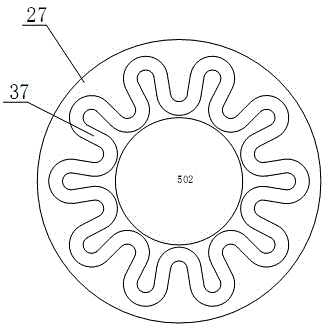
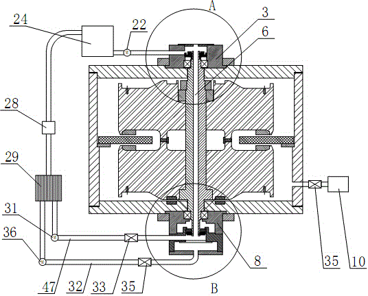
[0038] like Figure 4 As shown, in this embodiment, the upper bearing seat 3 is located above the upper bearing 4 , and an upper seal 42 is provided to separate the original upper oil cavity 21 into an upper shaft hole cavity 41 and an upper bearing cavity 43 . like Figure 5 As shown, in this embodiment, the lower bearing seat 8 is located below the lower bearing 7 , and a lower sealing member 45 and a separator 48 are provided to separate the original lower oil chamber 34 into a lower bearing chamber 44 and a lower shaft hole chamber 46 . like image 3 As shown, the upper shaft hole 41 and the lower shaft hole 46 are communicated with the shaft hole 6 , the upper shaft hole 41 is communicated with the upper oil pipe 23 , and the lower shaft hole 46 is communicated with the first oil return pipe 47 . The upper bearing cavity 43 and the lower bearing cavity 44 are communicated with the inner cavity of the container, and the lower bearing cavity 44 is communicated with the oi...


PUM


Abstract

The invention discloses a cooling system of a flywheel energy storage device. The flywheel energy storage device consists of a shell and an internal disc-type motor, wherein the shell has a vacuum sealing structure; an upper oil cavity and a lower oil cavity are respectively arranged at the upper part and lower part of the shell; the shell internally comprises at least one set of flywheel; a center shaft of each flywheel is a hollow mandrel, and an axle hole is formed in the center of the center shaft and is communicated with the upper oil cavity and the lower oil cavity; an oil tank is arranged outside the shell; the oil tank is communicated with the upper oil cavity by an upper oil pipe and is communicated with the lower oil cavity by an oil return pipe; the oil return pipe is provided with a third valve, an oil pump and a radiator. The cooling system can be used for cooling a rotor by the axle hole, so that a great deal of heat of the rotor which rotates at a high speed can be taken away in time, and safe and stable operation of the flywheel energy storage device is guaranteed. An upper bearing, a lower bearing and a stator disc are cooled in time by part of cooling oil, and the bearings can be lubricated, so that the reliable work of key parts can be guaranteed, and the defects of cavitation and the like of a pump caused by low pressure can be avoided.

Description

technical field [0001] The invention relates to the field of electric equipment, in particular to a heat dissipation system of a flywheel energy storage device. Background technique [0002] As an alternative to chemical batteries and supercapacitors, flywheel energy storage systems have the advantages of long life, low maintenance, high efficiency and high power. The flywheel energy storage relies on the inertia of the rotating flywheel rotor to convert electrical energy into kinetic energy and store it to realize uninterrupted power supply in the event of a power outage. When the flywheel rotates at high speed for a long time, the calorific value of the rotor is relatively large. In the case of concentrated discharge of large current, the calorific value of the stator is relatively large. If the heat cannot be dissipated in time, the excessive temperature will cause damage to the stator and rotor, resulting in The entire machine is damaged. At the same time, the flywheel...

Claims


Application Information

Patent Timeline
Patent Type & Authority Applications(China)
IPC IPC(8): H02K9/19
CPCH02K9/19F16F15/315F16F2222/025H02K1/32H02K7/025H02K9/193Y02E60/16
Inventor 李文圣崔小兵李云飞
Owner ERZHONG DEYANG POWER TECH CO LTD
Why Eureka
Try Eureka