Spiral bit capable of conveniently drilling into soil of deep scarification cultivation machine

A technology of auger bit and cultivator, which is applied to agricultural machinery and implements, applications, plows, etc. It can solve the problems of high resistance to entry into the soil, short service life, and low practicability, so as to prolong the service life, avoid wear and tear, and have a simple structure Effect

Active Publication Date: 2015-05-06
GUANGXI WUFENG MACHINERY CO LTD
View PDF9 Cites 23 Cited by
  • Summary
  • Abstract
  • Description
  • Claims
  • Application Information

AI Technical Summary

Problems solved by technology

However, the helical blades of the above-mentioned rotary grinding type deep plowing powder ridge multifunctional machinery lack the auxiliary mechanism for entering the soil,

Method used


Image

  • Spiral bit capable of conveniently drilling into soil of deep scarification cultivation machine
  • Spiral bit capable of conveniently drilling into soil of deep scarification cultivation machine

Examples


Embodiment 1

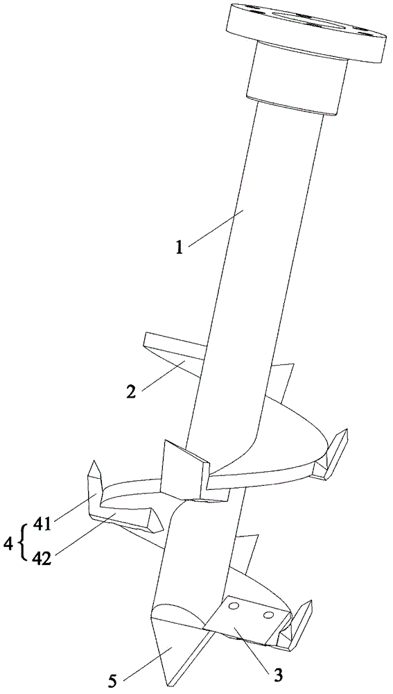
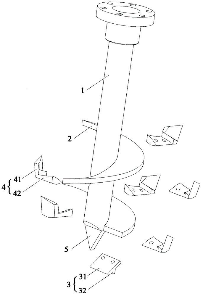
[0023] Such as figure 1 , figure 2 As shown, the direction of this embodiment is figure 1 The placement direction of the auger bit of the subsoil tillage machine that is easy to enter the soil shown in the present embodiment is an auger bit of the subsoil tillage machine that is easy to enter the soil. It includes a drill rod 1, a spiral blade 2, and a spiral blade 2 around Located at the lower part of the drill pipe 1, it also includes a soil-entering blade 3, which is arranged at the tail of the spiral blade 2 and located on the lower surface of the spiral blade 2. The invention has a simple structure. During farming operations, the drill rod 1 moves forward with the subsoiling tiller while rotating. Because the bottom surface of the tail of the spiral blade 2 is provided with a soil inserting blade 3, it is convenient for the drill rod 1 to enter the soil while rotating. It can effectively prevent the spiral blade 2 from being worn out, prolong the service life of the spira...

Embodiment 2

[0032] The difference between this embodiment and the first embodiment is that: in this embodiment, the diameter of the spiral blade 2 gradually changes from large to small along the direction of the drill rod 1 toward the bottom end of the drill rod 1. This embodiment breaks through the traditional spiral blades 2 with the same upper and lower diameters, and adopts the spiral blades 2 with the upper and lower diameters, which not only enhances the soil penetration rate of the spiral drill bit of the present invention, but also makes the soil on the surface of the ground smash relatively The deep soil is crushed finely and meets agronomic requirements.

[0033] The other structure of this embodiment is the same as that of the first embodiment, and will not be repeated here.

Embodiment 3

[0035] The difference between this embodiment and the first embodiment is that: in this embodiment, the cross section of the drill rod 1 is polygonal. The polygon can be triangle, quadrilateral, pentagon or hexagon, etc. The drill rod 1 is polygonal, so that when the drill rod 1 rotates, the angle of the polygon is equivalent to the cutter, which has the function of cutting soil, so the subsoil tiller When walking forward, the polygonal drill rod 1 can move forward while loosening the soil, further improving the farming efficiency. The polygon is not limited to a triangle, a quadrilateral, a pentagon or a hexagon, as long as the drill rod 1 is rotated to facilitate soil cutting.

[0036] The other structure of this embodiment is the same as that of the first embodiment, and will not be repeated here.


PUM


Abstract

The invention relates to the technical field of a drill bit, in particular to a spiral bit capable of conveniently drillinf into soil of a deep scarification cultivation machine. The spiral bit comprises a drill rod, a spiral blade and in-soil blades, wherein the spiral blade is arranged at the lower part of the drill rod, and the in-soil blades are arranged at the tail part of the spiral blade and are positioned on the lower surface of the spiral blade. The spiral bit disclosed by the invention has the advantages that the structure is simple, and the drill rod can move forwards along with the deep scarification cultivation machine while being rotated during ploughing operation; since the in-soil blades are arranged on the lower surface of the tail part of the spiral blade, the drill rod can be conveniently drilled into the soil while being rotated, meanwhile, the spiral blade can be effectively prevented from being abraded, the service life of the spiral blade is prolonged, and the practicability is high.

Description

Technical field [0001] The invention relates to the technical field of drill bits, in particular to an auger bit of a subsoiling tiller which is convenient to enter the soil. Background technique [0002] The main function of tillage equipment is deep ploughing and deep loosening of the land. In the past, deep ploughing and deep soiling machines used tractors as the platform and used old traditions such as plowing, hitting and harrowing. The process was complicated and the efficiency was low, and they needed to work when the cultivated land was wet and soft. The farming time is short and the farming depth is shallow, which is not conducive to agricultural production. Therefore, the traditional methods can no longer adapt to the large area of ​​land that needs deep ploughing and deep loosening. For this reason, the current automated deep ploughing and deep loosening has appeared. [0003] A Chinese utility model patent application with application number 201020514808.9 discloses a ...

Claims


Application Information

Patent Timeline
IPC IPC(8): A01B13/08
Inventor 李阳铭
Owner GUANGXI WUFENG MACHINERY CO LTD
Why Eureka
Try Eureka