
Proximal Humerus Plate

A technology of bone plate and proximal end, applied in the direction of outer plate, internal bone synthesis, fixer, etc., can solve the problems of blood supply at the front end of the humeral head, collapse of the front end of the humeral head, poor stability of the bone plate, etc., to avoid the front end Injury, bone loss reduction, good stability

Inactive Publication Date: 2019-01-22
奥斯泰克医疗器械(苏州)股份有限公司
View PDF5 Cites 0 Cited by
  • Summary
  • Abstract
  • Description
  • Claims
  • Application Information

AI Technical Summary

Problems solved by technology

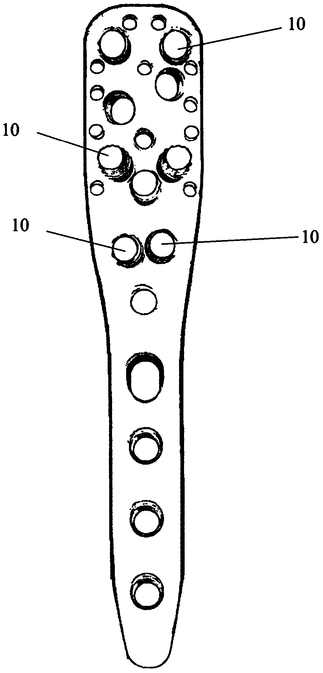
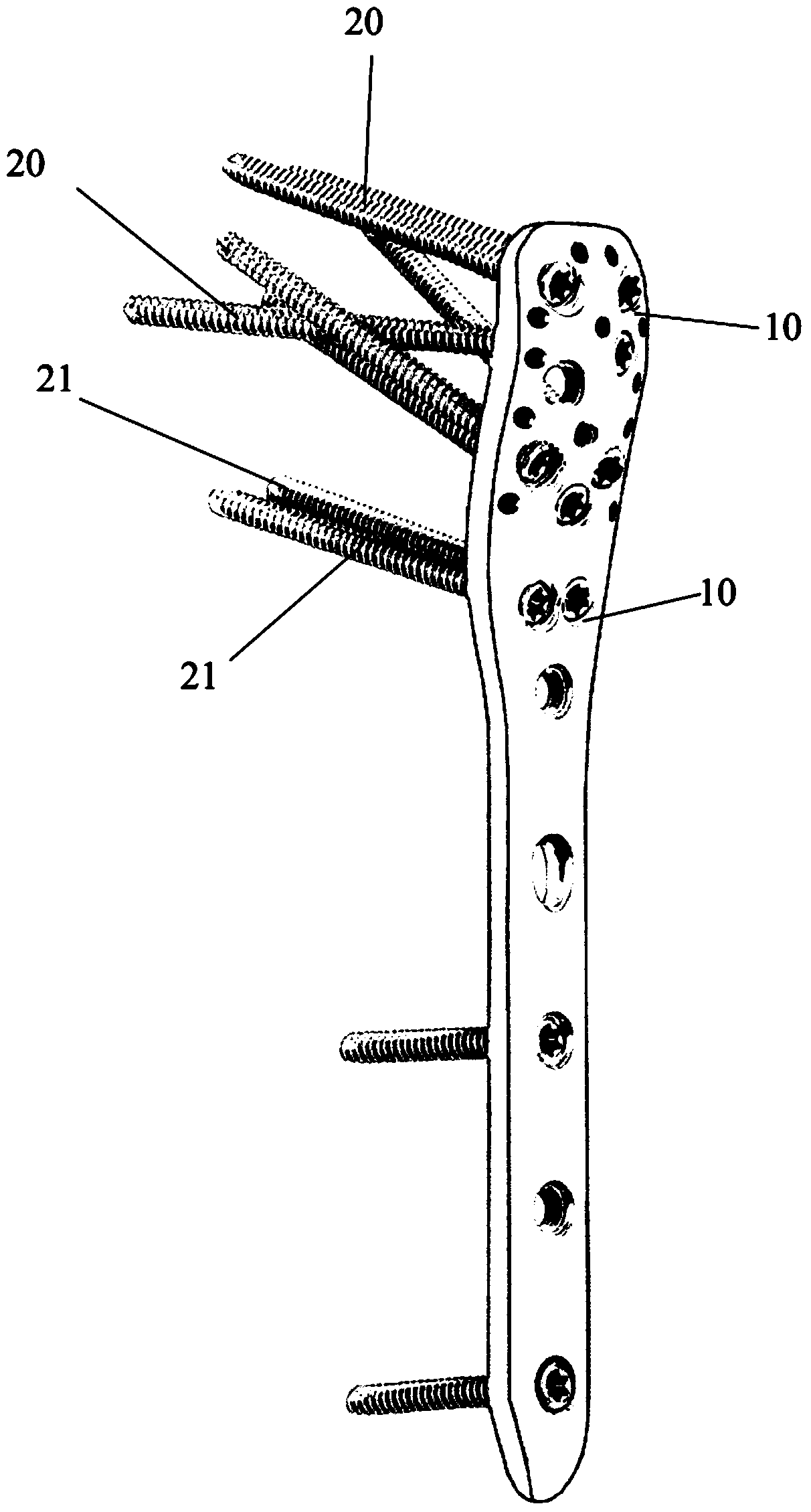
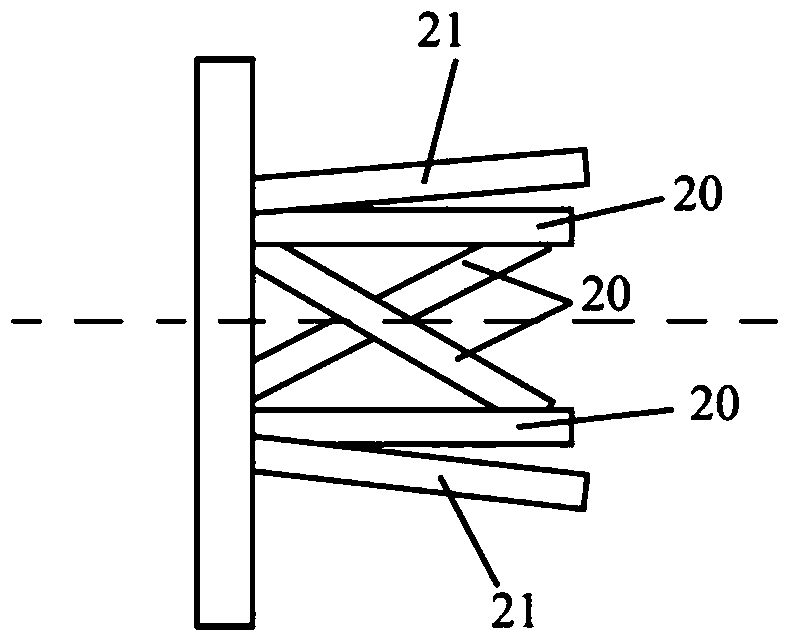
[0006] First of all, because the humeral head has a retroversion angle of about 30 degrees, the area of ​​the humeral head facing the bone plate is only its front end. Therefore, the front end of the humeral head fixed by the above bone plate is relatively densely distributed. screw 20 and screw 21, which will cause the blood supply of the front end of the humeral head to be greatly affected, thereby easily causing necrosis of the humeral head; In addition, the screws 20 and 21 are only distributed at the front end of the humeral head, which will also make the holding force provided by the multiple screws 20 insufficient, and make the force on the front end of the humeral head more concentrated, which will lead to the stability of the bone plate The sex is poor, and it is also easy to cause damage to the front end of the humeral head

Method used


Image

  • Proximal Humerus Plate
  • Proximal Humerus Plate
  • Proximal Humerus Plate

Examples


Embodiment Construction

[0033] Specific embodiments of the present invention will be described in detail below in conjunction with the accompanying drawings. It should be understood that the specific embodiments described here are only used to illustrate and explain the present invention, and are not intended to limit the present invention.

[0034] Please see Figure 4 and Figure 5 , Figure 4 A schematic diagram of an embodiment of the proximal humeral bone plate provided by the present invention; Figure 5 for Figure 4 Schematic top view of the proximal humeral plate shown. In this embodiment, the proximal humeral bone plate 1 is provided with a plurality of screw holes 10, and the multiple screw holes 10 are used (when the humeral head is fixed on the proximal humeral bone plate) to pass through multiple The screws 2 in each screw hole 10 can be placed in different regions of the humeral head, and the average value of the posterior inclination angles of the central axes of the plurality of...


PUM


Abstract

The invention relates to a humerus near end bone fracture plate. A plurality of screw holes are formed in the humerus near end bone fracture plate; screws capable of penetrating through the plurality of screw holes can be arranged into different regions of a humerus head through the plurality of screw holes; the average value of rear inclined angles of the middle axes of the plurality of screw holes is more than 0 degree. The middle axes of the plurality of screw holes in the humerus near end bone fracture plate are wholly and backwards inclined so that the screws penetrating through the plurality of screw holes can be uniformly distributed in the whole region of the humerus head; more screws are prevented from being arranged in the front end part of the humerus head so that the influences on blood supply of the front end part of the humerus head, caused by the arranged screws, are reduced and the front end of the humerus head is prevented from thanatosis; excessive bone mass of the front end part of the humerus head also can be prevented from being lost and the front end part of the humerus head is prevented from being collapsed. Furthermore, the plurality of screws are more uniformly distributed in the humerus head and the holding force provided by the plurality of screws is greater; the stress on each region of the humerus head is more uniform and the stability of the bone fracture plate is better; the damages to the front end part of the humerus head are avoided.

Description

technical field [0001] The invention relates to the field of medical instruments for treating fractures, in particular to a proximal humerus bone plate for treating fractures of the proximal humerus. Background technique [0002] When treating a fracture, after the broken bone is reset, it is generally necessary to use a bone plate to firmly connect and fix the broken bone together. The bone plate can avoid the displacement of the bone, and it is convenient for the patient to perform early functional exercise, so that the fractured bone can recover its function to the greatest extent. Fractures occurring at the proximal humerus are the most likely and one of the most common types of fractures, accounting for about 6-7% of all fractures. [0003] figure 1 It is a schematic diagram of an existing bone plate for treating proximal humeral fractures; figure 2 For screw mounting on figure 1 Schematic representation of the bone plate shown; image 3 It is a schematic top view...

Claims


Application Information

Patent Timeline
Patent Type & Authority Patents(China)
IPC IPC(8): A61B17/80
CPCA61B17/80A61B17/8052
Inventor 不公告发明人
Owner 奥斯泰克医疗器械(苏州)股份有限公司
Learn More