Automatically-controlled internal cooling system for cutting tool for numerically-controlled machine tool

A CNC machine tool, internal cooling technology, applied in the direction of manufacturing tools, metal processing machinery parts, maintenance and safety accessories, etc., can solve the problems of reducing the service life of the tool, adjusting the flow rate of the tool, waste of coolant and energy, etc., to protect the tool Effect

Active Publication Date: 2015-05-06
JIANGSU YUANLI AVIA PRECISION MACHINE TOOL
View PDF10 Cites 19 Cited by
  • Summary
  • Abstract
  • Description
  • Claims
  • Application Information

AI Technical Summary

Problems solved by technology

The disadvantage of this cooling technology is that the flow rate is fixed and cannot be changed, and the flow rate cannot be adjusted according to the speed of the tool and the amount of heat generated. Waste of coolant and energy. In addition, the waste coolant after workpiece processing also pollutes the environment very seriously.
[0004] Moreover, the tool cooling of CNC machine tools is generally achieved by spraying coolant on the outer surface of the tool to achieve cooling purposes. This cooling method is simple and convenient, but it has limitations; first, the cooling method of spraying c...

Method used


Image

  • Automatically-controlled internal cooling system for cutting tool for numerically-controlled machine tool
  • Automatically-controlled internal cooling system for cutting tool for numerically-controlled machine tool

Examples


Embodiment Construction

[0026] The present invention will be further described in detail below in conjunction with the accompanying drawings, so that those skilled in the art can implement it with reference to the description.

[0027] It should be understood that terms such as "having", "comprising" and "including" as used herein do not entail the presence or addition of one or more other elements or combinations thereof.

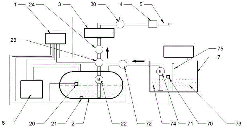
[0028] figure 1 An implementation form according to the present invention is shown, which includes:

[0029] Controller 1, used to control and coordinate the normal work of the whole system;

[0030] The cooling liquid storage tank 2 used to store the cooling liquid. The cooling liquid storage tank 2 is covered with a layer of insulation layer. The inside of the cooling liquid storage tank 2 is provided with a first liquid level sensor 20, a temperature sensor 21 and a first infusion pump 22. A liquid level sensor 20 can sense the liquid level of the cooling liquid and convert ...


PUM


Abstract

The invention discloses an automatically-controlled internal cooling system for a cutting tool for a numerically-controlled machine tool. The automatically-controlled internal cooling system comprises a controller, a coolant storage tank, a filter, a rotary joint and a machine tool cutting tool main shaft, wherein the coolant storage tank is internally provided with a liquid level sensor, a temperature sensor and an infusion pump; a liquid outlet pipeline and a liquid inlet pipeline are arranged outside the coolant storage tank; an electromagnetic proportional overflow valve and a pressure gauge are arranged on the liquid outlet pipeline; the filter is connected with the liquid outlet pipeline; a filter liquid outlet pipeline is arranged outside the filter; the rotary joint comprises a fixed end and a rotary end, wherein the fixed end is connected with the filter liquid outlet pipeline; a liquid conveying passage is arranged on the central axis of the machine tool cutting tool main shaft; one end of the machine tool cutting tool main shaft is connected with the rotary end of the rotary joint, and the other end of the machine tool cutting tool main shaft is connected with the machine tool cutting tool; a liquid outlet of the infusion pump is connected with the liquid outlet pipeline; a feedback electric signal generated by the liquid level sensor, the temperature sensor and the electromagnetic proportional overflow valve is accessed into the controller; the machine tool cutting tool main shaft is internally provided with an infusion through hole.

Description

technical field [0001] The invention relates to a cooling system for machine tools. More specifically, the present invention relates to an automatically controllable internal cooling system for CNC machine tools. Background technique [0002] Machine tool processing uses the relative movement between the tool and the workpiece to cause elastic and plastic deformation of the workpiece to achieve the purpose of metal processing. During the processing, due to the friction between the tool and the workpiece, a large amount of heat will be generated in the processing area. If the heat is not dissipated in time, the tool and the workpiece will be damaged, which will not only reduce the service life of the tool, but also affect the machining accuracy and surface of the workpiece. Therefore, the cooling effect of the tool cooling system of the machine tool has decisive significance for the machining quality, machining efficiency and tool life of the workpiece. [0003] During the ...

Claims


Application Information

Patent Timeline
IPC IPC(8): B23Q11/10
CPCB23Q11/1053
Inventor 王立民袁旎呼如亮吴亚辉朱云云
Owner JIANGSU YUANLI AVIA PRECISION MACHINE TOOL
Why Eureka
Try Eureka