Honing head

A honing head and honing technology, applied in the direction of honing tools, etc., to achieve the effect of slowing mutual impact, preventing relative displacement and ensuring synchronization

Inactive Publication Date: 2015-05-06
CHENGDU KESHENG PETROLEUM TECH
View PDF10 Cites 0 Cited by
  • Summary
  • Abstract
  • Description
  • Claims
  • Application Information

AI Technical Summary

Problems solved by technology

Aiming at the deficiencies in the prior art, the present invention makes certain improvements to the existing honing head to solve the problem of ensuring that the operating state between the oil stone and the base remains stable after the roughness of the inner surface of the workpiece disappears, and preventing the occurrence of Relative displacement, in order to achieve the purpose of prolonging the service life of the device; when the invention works, put the whetstone in the workpiece, and drive the honing body at the same time to realize the honing process of the whetstone on the inner wall of the workpiece, when the roughness of the inner wall of the workpiece is reduced to the processing standard At this time, the distance between the oil stone and the inner wall of the workpiece increases, that is, the adjustment rod located in the middle of the honing body starts to be driven, and the adjustment rod moves down until the outer circular surface of the conical protrusion directly cooperates with the inclined surface on the movable end of the adjustment pin , so that the adjusting pin moves outward along the radial direction of the honing body to realize the gap between the oil stone and the inner wall of the workpiece, and finally realize the fine honing of the inner wall of the workpiece;

Method used


Image

  • Honing head
  • Honing head

Examples


Embodiment 1

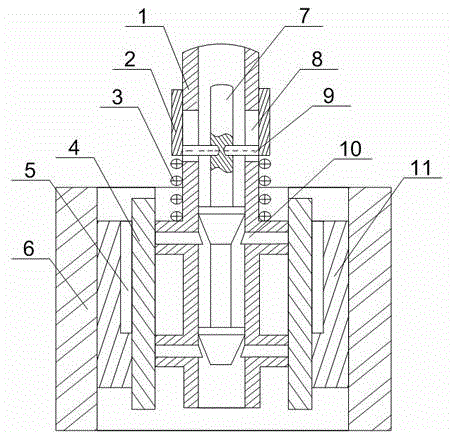
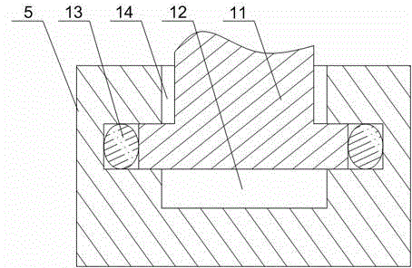
[0023] like figure 1 and figure 2 As shown, this embodiment includes a hollow honing body 1 and a plurality of spacers 4, a plurality of transition holes are opened on both sides of the honing body 1, and an adjustment pin 10 is fixed on one side of the spacer 4, and the adjustment The pin 10 cooperates with the gap 14 of the transition hole, and a fixing seat 5 is installed on the other side of the cushion block 4, and a groove 12 is provided on the fixing seat 5, and blind holes are respectively arranged on the two side walls of the groove 12, and the cross section is The main body of the horizontal part of the T-shaped oil stone 11 is placed in the groove 12 and the two ends of its horizontal part are placed in the blind hole. There is a gap 14 between the vertical part of the oil stone 11 and the groove 12, and in the blind hole There is a rubber strip 13 between the horizontal part of the whetstone 11; the inside of the honing body 1 is slidably provided with an adjustm...


PUM


Abstract

The invention discloses a honing head which comprises a honing body and a plurality of cushion blocks, wherein a plurality of transitional holes are formed in both sides of the honing body, adjusting pins are fixed on one side of the cushion blocks, the adjusting pins are in clearance fit with the transitional holes, fixed seats are installed on the other side of the cushion blocks, blind holes are respectively formed in both side walls of grooves, a main body of the horizontal part of an oil stone is arranged in the grooves, both ends of the horizontal part of the oil stone are arranged in the blind holes, and rubber strips are arranged between the blind holes and the horizontal part of the oil stone; an adjusting rod is arranged in the honing body in a sliding mode, a plurality of tapered bulges are installed on the adjusting rod, and inclined surfaces which are matched with the external circular surfaces of the tapered bulges are formed on the free ends of the adjusting pins. According to the honing head, mutual impact between the oil stone and the fixed seats is reduced through deformation or deformation recovery of the rubber strips during operation, so as to prevent relative displacement between the fixed seats and the oil stone, guarantee operation synchronization of the fixed seats and the oil stone, and finally achieve the purpose of preventing the oil stone from being damaged.

Description

technical field [0001] The invention relates to a honing machine, in particular to a honing head. Background technique [0002] Honing is a cutting technology with broad prospects. It is not only a processing method that can improve surface roughness, but also a semi-finishing and Finishing process method. Honing does not require special conditions to enable parts to obtain precise dimensions, geometric accuracy, military and engineering machinery and other manufacturing industries. [0003] Honing processing belongs to finishing processing, which can obtain higher processing accuracy than general mechanical processing. It is characterized by the use of high-quality particulate abrasives made of consolidated abrasive oilstone. The particles can ensure a high level of processing accuracy, requiring abrasive particle size, mold Good consistency of hardness and structure requires high accuracy of mold size and shape, and in order to achieve small cutting and efficient cutting...

Claims


Application Information

Patent Timeline
Patent Type & Authority Applications(China)
IPC IPC(8): B24B33/08
CPCB24B33/08
Inventor 贺昶明
Owner CHENGDU KESHENG PETROLEUM TECH
Why Eureka
Try Eureka