
Ink jet head and control method thereof

A control method and technology of inkjet head, which are applied in the directions of inking device, printing, printing device, etc., can solve the problems of uneven speed or volume of ink droplets, etc.

Inactive Publication Date: 2015-05-06
KK TOSHIBA +1
View PDF3 Cites 14 Cited by
  • Summary
  • Abstract
  • Description
  • Claims
  • Application Information

AI Technical Summary

Problems solved by technology

In the inkjet head using this method, there is a problem that the pressure fluctuation generated in the pressure chamber deforms the actuator and propagates to the adjacent pressure chamber to cause "crosstalk", so that the velocity of the ink droplet ejected according to the image pattern or uneven volume

Method used


Image

  • Ink jet head and control method thereof
  • Ink jet head and control method thereof
  • Ink jet head and control method thereof

Examples


no. 1 approach

[0023] First, a first embodiment will be described.

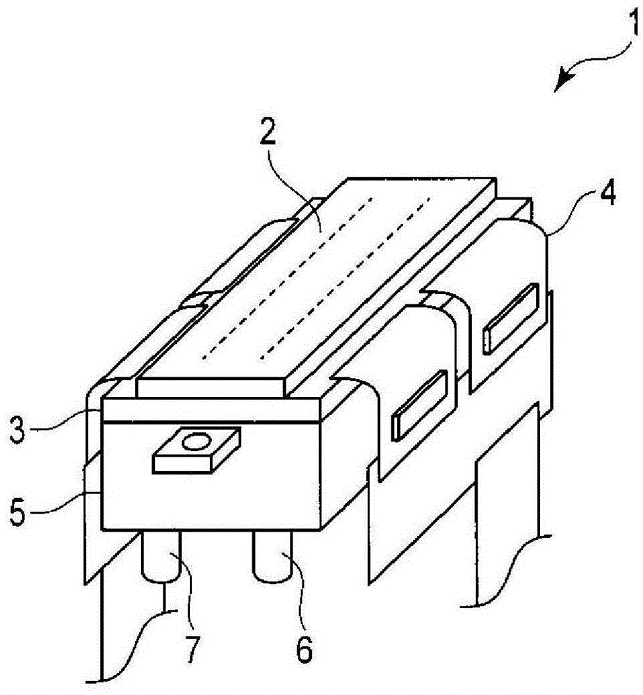
[0024] figure 1 It is a perspective view of the inkjet head 1 of the inkjet head recording device according to the first embodiment.

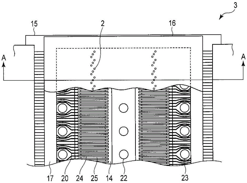
[0025] The inkjet head 1 includes: a head substrate 3 having nozzles 2 that eject ink; a driver IC 4 that generates drive signals; and a manifold 5 having ink supply ports 6 and ink discharge ports 7 .

[0026] The inkjet head 1 discharges the ink supplied from the ink supply port 6 from the nozzle 2 based on a drive signal generated by the drive circuit 4 . Among the inks flowing in from the ink supply port 6 , the ink not discharged from the nozzle 2 is discharged from the ink discharge port 7 .

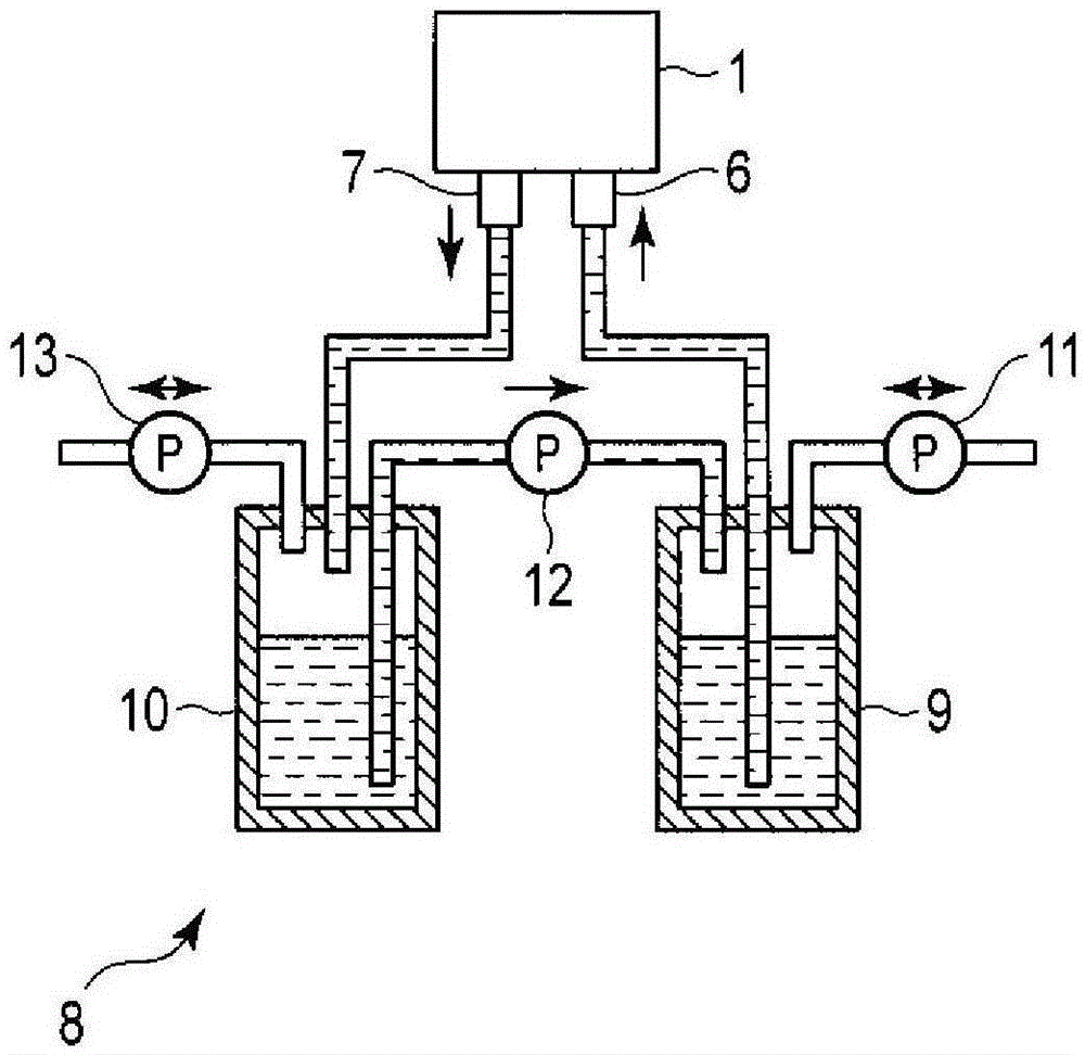
[0027] figure 2 It is a schematic diagram of the ink supply device 8 used in the inkjet head recording device of the first embodiment. The ink supply device 8 is composed of a supply-side ink cartridge 9, a discharge-side ink cartridge 10, a supply-side pressure regulating pump 11, a transfe...

no. 2 approach

[0058] Next, a second embodiment will be described.

[0059] exist Figure 7(a) , 7(b) In the above, the situation of controlling by the driving signal of the two-stage voltage level is described, and it can also be as follows Figure 9(a) , 9(b) The drive signals shown are controlled by three-stage voltage levels.


PUM


Abstract

In accordance with one embodiment, an ink jet head comprises a driving signal generator configured to apply rectangular waveform electric field pulse to a partition wall forming a pressure chamber for ejecting ink; wherein the driving signal generator applies, to a second partition wall adjacent to a first partition wall forming the pressure chamber for ejecting ink and a third partition wall adjacent to the second partition wall, electric field pulse including at least one rectangular waveform which is a rectangular waveform opposite to the electric field pulse applied to the adjacent first partition wall and has a pulse width determined based on the electric field pulse at the timing corresponding to the electric field pulse applied to the first partition wall, in a case of ejecting ink from any of the plurality of pressure chambers.

Description

technical field [0001] Embodiments of the present invention relate to an inkjet head and a control method thereof. Background technique [0002] Conventionally, there is known an inkjet head employing a so-called "common wall" system in which partition walls of adjacent pressure chambers are used as actuators. In the inkjet head using this method, there is a problem that the pressure fluctuation generated in the pressure chamber deforms the actuator and propagates to the adjacent pressure chamber to cause "crosstalk", so that the velocity of the ink droplet ejected according to the image pattern Or the volume is uneven. [0003] In response to such a problem, a technology has been disclosed in which pressure fluctuations are intentionally generated in a pressure chamber in which ink is not ejected by driving an actuator with virtual pulses, and the ejection speed or volume of ink droplets is compensated by crosstalk of the pressure fluctuations. The change. Contents of t...

Claims


Application Information

Patent Timeline
Patent Type & Authority Applications(China)
IPC IPC(8): B41J2/01B41J29/38
CPCB41J2/04525B41J2/04543B41J2/04573B41J2202/10B41J2202/12B41J2/04588B41J2/04596B41J2/04581B41J2/04591B41J2/04598B41J2/04593B41J2/04541
Inventor 日吉光幸仁田昇小野俊一
Owner KK TOSHIBA
Learn More