Inner spiral unit

An internal helix and helix technology, applied in the field of internal helix units, can solve the problems of inability to set up and use the structure design of single leaf and compound leaves, breakage of compound leaves, leakage and so on.

Inactive Publication Date: 2015-05-06
QUAN SIANG TECH DEV
View PDF5 Cites 1 Cited by
  • Summary
  • Abstract
  • Description
  • Claims
  • Application Information

AI Technical Summary

Problems solved by technology

[0004] 1. Because the hollow pipe body 10 is fixed and the spiral blade 30 rotates during the action, even if the inner wall surface of the hollow pipe body 10 is combined with the lining rubber 20, it cannot be completely sealed when the fluid (conveyor) is transported, and it will still There is leakage, and the flow rate is not stable
[0005] 2. Because the hollow pipe body 10 and the helical blade 30 do not rotate synchronously during the action, there will be a situation of being stuck between the hollow pipe body 10 and the helical blade 30 when the solid (transported object) is conveyed, and in severe cases it will Cause power source b idling damage
[0006] 3. After the solid (transported object) is conveyed, if the stuck condition is not eliminated, it will cause mildew and corruption for a long time, resulting in the contamination of the conveyed object during the conveying process; It is easy to produce chemical changes and release chemical substances to pollute the conveyed matter; and it is easy to break the spiral blade 30 due to long-term friction and stress concentration
[0007] 4. Increase the components lined with rubber 20, not only the failure rate is high, but also the maintenance is inconvenient
[0008] 5. If the hollow pipe body 10 is formed by solid connection of several pipe sections, the lack of poor connection strength and reduced adhesion will be further increased.
[0009] 6. If the helical blade 30 must have a single leaf part and a compound leaf part, because the hollow pipe body 10 and the helical blade 30 do not rotate synchronously during the action, the compound leaf part under strong pressure will break and separate Therefore, the existing helical blades 30 cannot be provided with and use the structural design of the single leaf portion and the compound leaf portion

Method used


Image

  • Inner spiral unit
  • Inner spiral unit
  • Inner spiral unit

Examples


Embodiment Construction

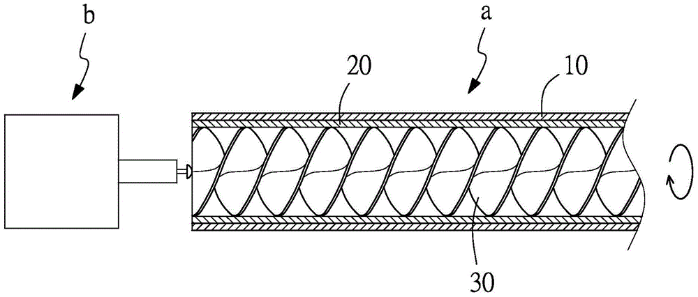
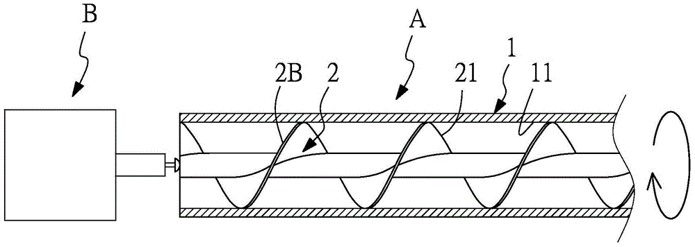
[0038] Such as figure 2 As shown, the present invention refers to an internal spiral unit, which mainly includes a spiral pipe A, and is powered by a power source B in addition, wherein:

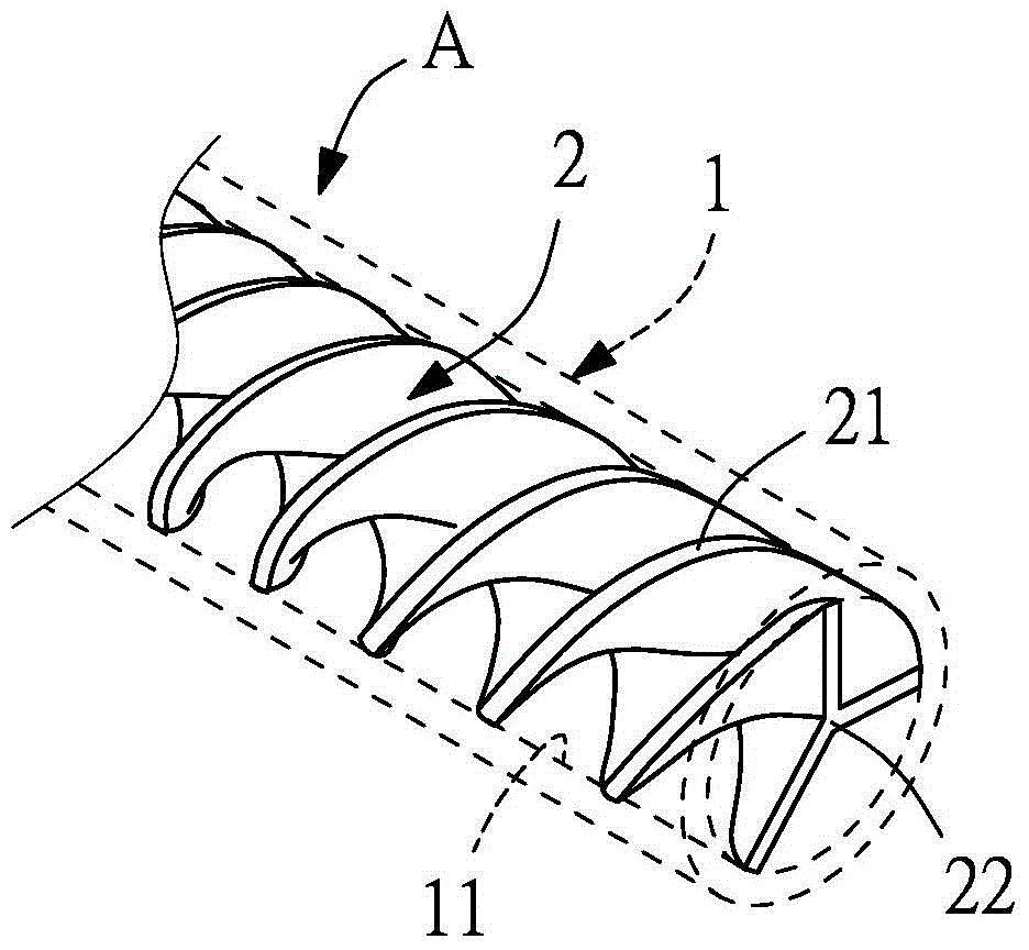
[0039] The spiral pipe fitting A comprises a hollow pipe body 1 and a helical blade 2 (such as figure 2 , 3 ), the hollow pipe body 1 has an inner wall surface 11, and the hollow pipe body 1 can be composed of several pipe sections 1A fixedly connected (another example Figure 4 ), and the helical blade 2 can also be composed of several blade segments 2A fixedly connected. The outer edge of the helical blade 2 is an outer edge 21, and the outer edge 21 and the inner wall surface 11 of the hollow pipe body 1 appear to be seamlessly affixed (also as the first Figure 5-7 , Figures 5A-7A ), so that when the hollow pipe body 1 or the helical blade 2 is rotated, they can all rotate synchronously.

[0040] The power source B can directly actuate the rotation of the screw blade 2 (such as ...


PUM


Abstract

The invention discloses an inner spiral unit. The inner spiral unit mainly adopts a spiral pipe fitting, and additionally uses a power source for generating power; the spiral pipe fitting has a spiral blade in a hollow pipe body; as the outer side edge of the spiral blade is in seamless fixed connection with the inner wall surface of the hollow pipe body, when the power source drives the hollow pipe body or the spiral blade to rotate, the spiral pipe fitting and the spiral blade can synchronously rotate; and because of the precession driving of the spiral blade in the hollow pipe body, the inner spiral unit can be applied to the conveying of fluids (such as water and oil) or solids (such as corn kernels, grains and plastics), or can be applied to such fields as spiral stirring and fluid power generation so as to achieve such multiple benefits as complete sealing, improvement of structural strength, stable flowing speed and long service life.

Description

technical field [0001] The invention relates to an internal helical unit, especially the internal helical unit in which the helical blade is seamlessly fixed to the inner wall surface of the hollow pipe body. Background technique [0002] In the field of machinery, there are many things to say about conveying devices for conveying fluids (such as water, oil, etc.), solids (such as corn kernels, grains, plastics, etc.) or gases, such as common conveyor belts for conveying solids, conveying liquids or gases Centrifugal pumps for mixing liquids, conveying devices for conveying liquids or gas-liquid mixtures or solids, etc. Take the internal screw conveying device as an example, such as figure 1 , which mainly has a helical pipe a and a power source b, the helical pipe a is composed of a hollow pipe body 10 combined with a lining rubber 20 on the inner wall, and is formed by a helical blade 30 axially pierced, and the power source b is mainly used to drive the spiral blade 30 ...

Claims


Application Information

Patent Timeline
Patent Type & Authority Applications(China)
IPC IPC(8): B65G33/14B65G33/26
CPCB65G33/14B65G33/265
Inventor 孙荣平
Owner QUAN SIANG TECH DEV
Why Eureka
Try Eureka