A method for erecting juxtaposed box girders in tunnels

An in-tunnel and box girder technology, applied in the erection/assembly of bridges, bridges, bridge construction, etc., can solve the problems of complex methods, difficult operation, high cost, and achieve the effect of high stability factor, reducing construction difficulty and saving time.

Active Publication Date: 2016-05-04
CHINA RAILWAY 23RD CONSTR BUREAU LTD
View PDF10 Cites 3 Cited by
  • Summary
  • Abstract
  • Description
  • Claims
  • Application Information

AI Technical Summary

Problems solved by technology

[0003] The purpose of the present invention is to overcome the above-mentioned deficiencies of complex method, long construction period, difficult operation and high cost brought about by the cast-in-place method for the construction of the head hole box girder in the bridge and tunnel engineering existing in the prior art, and provides A method for erecting and arranging box girders in tunnels

Method used


Image

  • A method for erecting juxtaposed box girders in tunnels
  • A method for erecting juxtaposed box girders in tunnels
  • A method for erecting juxtaposed box girders in tunnels

Examples


Embodiment Construction

[0037] The present invention will be further described in detail below in conjunction with test examples and specific embodiments. However, it should not be understood that the scope of the above subject matter of the present invention is limited to the following embodiments, and all technologies realized based on the content of the present invention belong to the scope of the present invention.

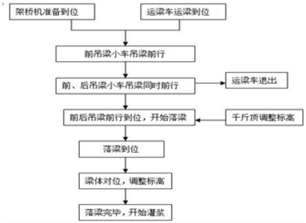
[0038] Such as figure 1 Shown is the flow chart of the method for erecting and arranging box girders in the tunnel 03 of the present invention. This specific embodiment adopts the TLC450 type bridge erecting machine 1, including the following steps:

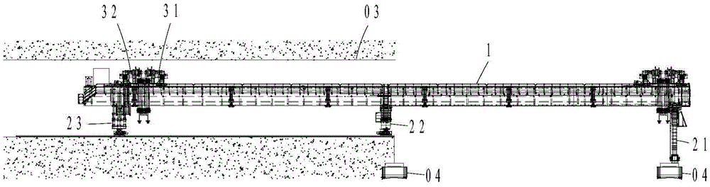
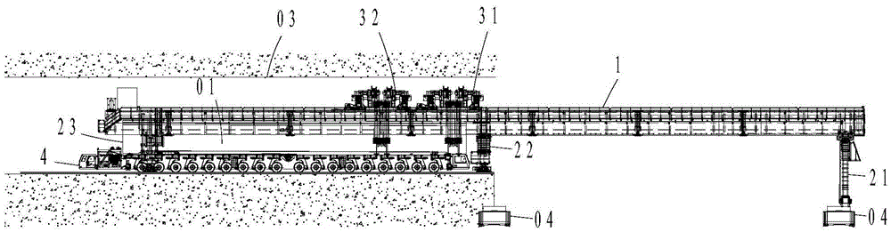
[0039] Step 1, the bridge erecting machine 1 passes through the tunnel 03; figure 2 As shown, the girder truck carries two brackets into the belly of the bridge erecting machine 1, and the girder trolley travels to the end of the main beam of the bridge erecting machine 1 as a counterweight; the beam truck is raised to the middle posi...


PUM


Abstract

The invention discloses a method for erecting parallel box girders in a tunnel. The method comprises the steps of making a bridge girder erection machine pass through the tunnel, wherein the bridge girder erection machine is conveyed to the position of the entrance of the tunnel by a girder transporting vehicle through two supports; placing the bridge girder erection machine in position, adjusting the height of the bridge girder erection machine to be matched with the height of the tunnel, making the height of a rear supporting leg, the height of a middle supporting leg and the height of a front supporting leg increase gradually, and making the surface of the bridge girder erection machine incline upwards horizontally; conducting girder feeding through the girder transporting vehicle; lifting the first box girder through the bridge girder erection machine; finishing girder feeding through the bridge girder erection machine; lowering and horizontally moving the first box girder through a front girder carrier and a rear girder carrier; taking the second box girder through the bridge girder erection machine in the same way and conducting lowering and horizontal movement of the girder; finishing girder erection. According to the method, due to the fact that the bridge girder erection machine is adopted to erect the parallel box girders in the tunnel, time is saved a lot, cost is reduced, erection of the first hole box girders with cast-in-place required in the prior art is achieved safely and smoothly, the difficulty of erecting the first hole parallel box girders in the specific tunnel-bridge connection environment is reduced, and construction safety and construction quality are guaranteed.

Description

technical field [0001] The invention relates to the field of bridge and tunnel engineering construction, in particular to a method for erecting and arranging box beams in a tunnel. Background technique [0002] Existing bridge erecting machines are mainly used for highway bridge erection, conventional railway track bridge erection and passenger-only railway bridge erection. For bridge erection projects connecting bridges and tunnels, since there are few or no roadbeds on both sides of the tunnel entrance, it cannot meet the existing requirements. Therefore, due to the inconvenience of transportation, the existing method of completing the first hole and juxtaposing the box girder, such as the full hall support method and the steel tube Bailey beam support method, etc. , the cast-in-place method is to bind the steel skeleton first, and weld the steel bars of the next section in one section of concrete. After the early strength of the concrete is formed, the joint surface is ch...

Claims


Application Information

Patent Timeline
Patent Type & Authority Patents(China)
IPC IPC(8): E01D21/00
CPCE01D21/06
Inventor 刘陈坤张教材南树宏杨俊东许晋豫刘延龙霍莉
Owner CHINA RAILWAY 23RD CONSTR BUREAU LTD
Why Eureka
Try Eureka