Rear crossbeam and main girder connecting structure for self-propelled movable formwork

A technology of moving formwork and connecting structure, applied in the direction of erecting/assembling bridges, bridges, bridge materials, etc., can solve the problems of lack of rotational freedom, stress concentration of connecting members, deviation from the bridge deck, etc., to avoid local bending stress concentration, The effect of reducing the requirement of structural strength and high construction safety

Inactive Publication Date: 2015-05-06
CHANGAN UNIV +1
View PDF6 Cites 11 Cited by
  • Summary
  • Abstract
  • Description
  • Claims
  • Application Information

AI Technical Summary

Problems solved by technology

[0004] (1) The rear end of the main girder is suspended on the rear cross beam. At this time, the center of gravity of the main girder is on the front side of the rear cross beam. Since the existing main girder and the rear cross beam only have relative freedom of movement in the direction of the cross bridge, there is no movement around the cross bridge. The degree of freedom of rotation to the axis, so the local transverse bending moment at the connection between the rear beam and the main beam is relatively large, and the connecting members are prone to stress concentration, and the requirements for structural strength are too high
[0005] (2) The rear end of the main girder is suspended on the rear beam. When the mobile formwork is in the mold opening state, the center of gravity of the main girder and its accessories deviates from the center of the suspension mechanism towards the inner side of the bridge. Since there is only a cross bridge between the existing main girder and the rear beam There is no freedom of rotation around the axis of the longitudinal bridge, so the local longitudinal bending moment at the connection between the rear beam and the main beam is relatively large, and the connecting members are prone to stress concentration, and the requirements for structural strength are too high
[0006] (3) The rear end of the main beam is suspended on the rear beam. When the mobile formwork is opened and walked, there is no freedom of rotation around the vertical axis because the existing main beam and the rear beam only have relative movement freedom in the horizontal bridge direction. , so the rear beam and the main beam cannot rotate relatively around the vertical axis. When the bridge is located on a flat curve with a small radius, the mobile formwork will deviate from the bridge deck when walking across the bridge as a whole, which is not good for construction safety.

Method used


Image

  • Rear crossbeam and main girder connecting structure for self-propelled movable formwork
  • Rear crossbeam and main girder connecting structure for self-propelled movable formwork
  • Rear crossbeam and main girder connecting structure for self-propelled movable formwork

Examples


Embodiment Construction

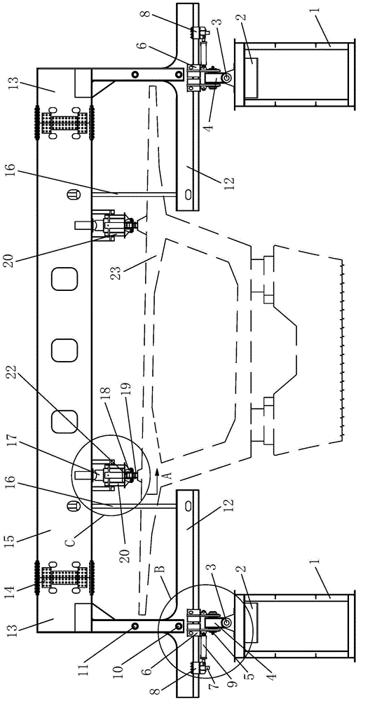
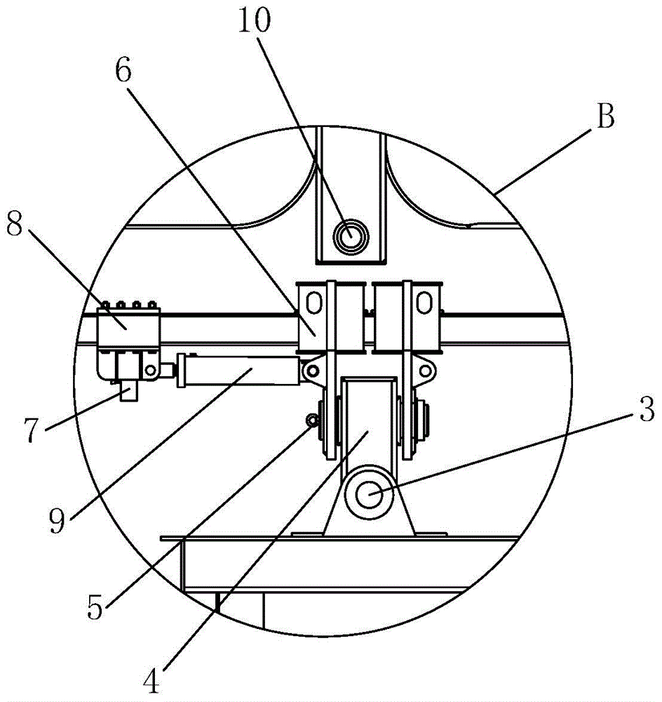
[0042] Such as figure 1 , figure 2 , Figure 4 , Figure 5 , Figure 8 with Picture 9 As shown, the present invention includes a three-axis rotation mechanism, the three-axis rotation mechanism includes a traverse frame 6, a hanging rod 4, lifting lugs 2, a traverse base 8 and a traverse cylinder 9, the lower end of the traverse frame 6 passes The transverse pin 5 is hinged to the upper end of the hanging rod 4, and the transverse pin 5 is arranged in a transverse bridge direction. The lower end of the hanging rod 4 is hinged to the upper end of the lifting lug 2 through the longitudinal pin 3, and the longitudinal pin 3 is longitudinally hinged. The horizontal movement cylinder 9 is arranged between the horizontal movement frame 6 and the horizontal movement base 8. One end of the horizontal movement cylinder 9 is hinged with the horizontal movement frame 6, and the other end of the horizontal movement cylinder 9 is connected to the horizontal movement frame 6. The moving ba...


PUM


Abstract

The invention discloses a rear crossbeam and main girder connecting structure for a self-propelled movable framework. The rear crossbeam and main girder connecting structure comprises a triaxial rotating mechanism; the triaxial rotating mechanism comprises transverse moving frames, hanging rods, lifting lugs, transverse moving bases and transverse moving oil cylinders, wherein the lower end of each transverse moving frame is hinged to the upper end of the corresponding hanging rod through a transverse pin shaft; each transverse pin shaft is arranged in a transverse direction; the lower end of each hanging rod is hinged to the upper end of the corresponding lifting lug through a longitudinal pin shaft; each longitudinal pin shaft is arranged in a longitudinal direction; two ends of each transverse moving oil cylinder are respectively hinged to the corresponding transverse moving frame and the corresponding transverse moving base; each transverse moving frame and the corresponding transverse moving base are respectively suspended on a rear crossbeam of the self-propelled movable formwork; each transverse moving base is connected with a rear crossbeam of the self-propelled moving formwork; each transverse moving frame is positioned in the inner side of the corresponding transverse moving base; the lower part of each lifting lug extends to a main girder of the self-propelled moving formwork, and the main girder of the self-propelled moving formwork can rotate around the lifting lugs; the lifting lugs are vertically arranged. According to the rear crossbeam and main girder connecting structure disclosed by the invention, the stress concentration phenomenon generated when local transverse and longitudinal bending moments at the connecting part between the rear crossbeam and the main girder are relatively large is avoided, and the safety of small-radius horizontal curve bridge construction is ensured.

Description

Technical field [0001] The invention belongs to the technical field of a self-propelled movable formwork, and particularly relates to a connection structure of a rear cross beam and a main beam of a self-propelled movable formwork. Background technique [0002] The mobile formwork is a kind of self-contained formwork, which uses the platform or pier as the support to cast the bridge on-site. As an advanced construction equipment, due to the advantages of good construction quality, easy operation and high efficiency, the mobile formwork has been widely used in the continuous beam construction of expressways, highway bridges and railway bridges. [0003] Mobile mold bases are divided into two types: self-propelled mobile mold bases and non-self-propelled mobile mold bases. Self-propelled mobile mold bases are widely used because of their self-propelled functions. The traveling of the self-propelled mobile formwork is realized by longitudinal movement of the propulsion trolley at the...

Claims


Application Information

Patent Timeline
Patent Type & Authority Applications(China)
IPC IPC(8): E01D21/00
CPCE01D21/00E01D2101/24
Inventor 邵雨虹王斌华雷江王龙奉王瑞
Owner CHANGAN UNIV
Why Eureka
Try Eureka