Formwork support system and construction method of cast-in-place concrete beam-slab structure

A technology for supporting concrete beams and formwork, which is applied in the field of construction engineering, can solve the problems such as the inability to share beam formwork support poles, the difficulty of erecting beam plate formwork support poles, the difficulty of connecting poles and horizontal poles, and the like. The effect of easy quality control, consumption saving and easy connection

Inactive Publication Date: 2016-10-26
FUJIAN UNIV OF TECH +1
View PDF6 Cites 0 Cited by
  • Summary
  • Abstract
  • Description
  • Claims
  • Application Information

AI Technical Summary

Problems solved by technology

[0002] At present, in construction projects, for the formwork support system of cast-in-place concrete beam and slab structures, most of them use fastener-type steel pipe scaffolding or bowl-buckle-type steel pipe scaffolding, and the top of the fastener-type steel pipe scaffolding or bowl-buckle steel pipe scaffolding pole is adjustable. Jacking, then lay joists on the adjustable jacking, set joists on the joists, and then install beam slab formwork on the joists. This support system has the incompatibility between beam formwork support poles and floor formwork support poles. Common use leads to an increase in the amount of support poles, and it is difficult to erect the support poles of the beam-slab formwork, resulting in complex installation processes and low installation efficiency
When the formwork support pole adopts the traditional adjustable steel pipe column, because the diameter of the inner casing and the outer casing of the column is different, which is inconsistent with the specification of the traditional horizontal rod, it is difficult to connect the vertical rod and the horizontal rod, and the quality is difficult to guarantee

Method used


Image

  • Formwork support system and construction method of cast-in-place concrete beam-slab structure
  • Formwork support system and construction method of cast-in-place concrete beam-slab structure
  • Formwork support system and construction method of cast-in-place concrete beam-slab structure

Examples


Embodiment Construction

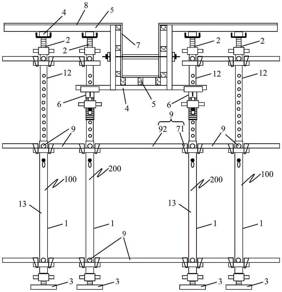
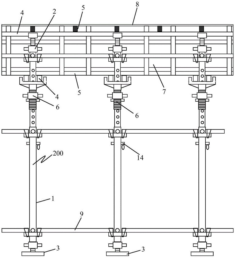
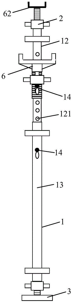
[0042] see Figure 1 to Figure 10 As shown, the present invention is a formwork support system for cast-in-place concrete beam-slab structures. The support system includes multiple sets of support rod assemblies, and each set of support rod assemblies includes: a first support rod assembly 100 and a second support rod assembly 200; The first support rod assembly 100 includes a telescopic support pole 1, an adjustable jack 2, an adjustable base 3, a joist 4, and a joist 5; the telescopic support pole 1 is covered with a plurality of trays 11. The adjustable jacking 2 is set on the top of the telescopic support pole 1, and the adjustable base 3 is set on the bottom of the telescopic support pole 1;

[0043] The second support rod assembly 200 is provided with a girder 6 on the telescopic support pole 1 of the first support rod assembly 100; the joist 4 is arranged on the girder 6 or on the adjustable jacking 2 , the joists 5 are arranged on the joists 4; the second support rod ...


PUM


Abstract

The invention provides a structure template supporting system for a cast-in-place concrete beam plate. The supporting system comprises a plurality of groups of supporting rod components, wherein each group of supporting rod components comprises a first supporting rod component and a second supporting rod component; each first supporting rod component comprises a telescopic supporting vertical rod, an adjustable top support, an adjustable base, a supporting beam and a joist; a plurality of trays are arranged on the telescopic supporting vertical rods in a sleeving mode; the adjustable top supports are arranged on the tops of the telescopic supporting vertical rods, and each second supporting rod component is formed in a manner that the beam support is additionally arranged on the telescopic supporting vertical rod of the first supporting rod component; the beam supports are arranged on the beam supports or the adjustable top supports, and the joists are arranged on the supporting beams; a horizontal rod is arranged on trays of the two adjacent telescopic supporting vertical rods, and the trays of all telescopic supporting vertical rods are connected to form the supporting system. The invention further provides a construction method for the structure template supporting system. The structure template supporting system is simple in structure and convenient to operate, so that the construction quality is improved.

Description

technical field [0001] The invention relates to the technical field of construction engineering, in particular to a formwork support system and construction method for cast-in-place concrete beam-slab structures. Background technique [0002] At present, in construction projects, for the formwork support system of cast-in-place concrete beam and slab structures, most of them use fastener-type steel pipe scaffolding or bowl-buckle-type steel pipe scaffolding, and the top of the fastener-type steel pipe scaffolding or bowl-buckle steel pipe scaffolding pole is adjustable. Jacking, then lay joists on the adjustable jacking, set joists on the joists, and then install beam slab formwork on the joists. This support system has the incompatibility between beam formwork support poles and floor formwork support poles. Common use leads to an increase in the amount of supporting poles, and it is difficult to erect the beam-slab formwork supporting poles, resulting in complex installatio...

Claims


Application Information

Patent Timeline
Patent Type & Authority Patents(China)
IPC IPC(8): E04G11/48
Inventor 周继忠郑永乾郑莲琼庄金平蔡雪峰张雪丽温骏荣邱爱琴李小明
Owner FUJIAN UNIV OF TECH
Why Eureka
Try Eureka