Wavelength division multiplexer/de-multiplexer and optical transmitter module

A technology of optical emission components and wavelength division multiplexing, which is applied in the field of optical communication and can solve the problems of unfavorable optical path combining, offset, and many reflection times.

Inactive Publication Date: 2015-05-06
HISENSE BROADBAND MULTIMEDIA TECH
View PDF6 Cites 4 Cited by
  • Summary
  • Abstract
  • Description
  • Claims
  • Application Information

AI Technical Summary

Problems solved by technology

[0005] Although the above prior art realizes combining four channels of light with different wavelengths into one channel of light, there are six light reflection points in the combiner, and the incident light λ 1 After six reflections, the incident light λ 2 After four reflections, the incident light λ 3 After two reflections, the four-way light has a total of twelve reflections, and the light has more reflections in the combiner
[0006] At the same time, due to the existence of errors, the incident angle of the high-reflection film will shift, and the angle difference between the incident light and the normal will be reflected between the reflected light and the normal, that is, how much the incident angle shifts, the reflection The angle is also offset by how much, resulting in the angular offset value of the incident light and the reflected light being twice the angle difference. Then, after multiple reflections, the cumulative offset of this angle difference will be very large, and the incident position after reflection will be A large offset occurs, which is not conducive to the merging of subsequent optical paths

Method used


Image

  • Wavelength division multiplexer/de-multiplexer and optical transmitter module
  • Wavelength division multiplexer/de-multiplexer and optical transmitter module
  • Wavelength division multiplexer/de-multiplexer and optical transmitter module

Examples


Embodiment 1

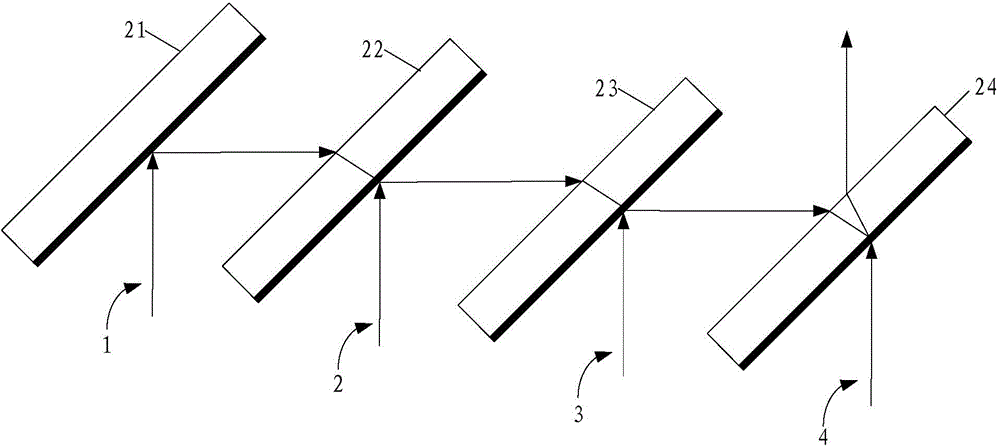
[0034] An embodiment of the present invention provides a wavelength division multiplexing / demultiplexing device, such as figure 2As shown, the wavelength division multiplexer / demultiplexer is used to multiplex at least four optical signals into one optical signal, and the wavelength division multiplexer / demultiplexer includes: an optical path changing element 21, a first filtering and combining optical element 22 . The second filtering light combining element 23 , and the third filtering light combining element 24 .

[0035] Wherein, the optical path changing element 21 is used to reflect the first optical signal 1 among the at least four optical signals, and input it to the first filtering and combining element 22;

[0036] The first filtering and combining element 22 is used to reflect the second optical signal 2 out of at least four optical signals, and transmit the input first optical signal 1, so that the second optical signal 2 and the first optical signal The optical ...

Embodiment 2

[0055] An embodiment of the present invention provides a light emitting component, such as Figure 8 As shown, the light-emitting component includes: a first laser chip 41, a second laser chip 42, a third laser chip 43, a fourth laser chip 44, and any one of the first embodiment for different wavelengths of light A wavelength division multiplexer / demultiplexer for multiplexing signals.

[0056] Figure 8 only with Image 6 The shown wavelength division multiplexing / demultiplexing device multiplexes different optical signals into one optical signal as an example for illustration. Among them, the first laser chip 41 is used to output the first optical signal 1 to the optical path changing element 21; the second laser chip 42 is used to output the second optical signal 2 to the first filter optical combination element 22; the third laser The chip 43 is used to output the third optical signal 3 to the second filtering and combining element 23 ; the fourth laser chip 44 is used ...

Embodiment 3

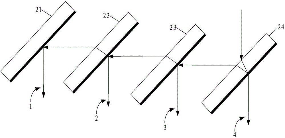
[0062] An embodiment of the present invention provides a light emitting component, such as Figure 10 As shown, the light emitting assembly includes: a first photodetector 71, a second photodetector 72, a third photodetector 73, a fourth photodetector 74, and any one of the first photodetectors for A wavelength division multiplexer / demultiplexer for separating optical signals of different wavelengths.

[0063] Figure 10 only with Figure 7 The shown wavelength division multiplexer / demultiplexer is used as an example to illustrate the separation of mixed optical signals. Wherein, the fourth photodetector 74 is used to receive the fifth optical signal 5 transmitted by the third filtering light combining element 24; the third photodetector 73 is used to receive the sixth optical signal reflected by the second filtering light combining element 23 6. The second photodetector 72 is used to receive the seventh optical signal 7 reflected by the first filtering light combining elem...


PUM


Abstract

The embodiment of the invention discloses a wavelength division multiplexer/de-multiplexer and an optical transmitter module and relates to the communication technology field. The wavelength division multiplexer/de-multiplexer is used for reducing the reflection number of light signals and improving the combination of light paths. At least four paths of light signals are multiplexed into one path of light signals by the wavelength division multiplexer/de-multiplexer, different light signals are reflected or transmitted through a light path changing element, a first filtering light combination element, a second filtering light combination element and a third filtering light combination element, so that the light signals with different wavelengths can be multiplexed into one path of light signals.

Description

technical field [0001] The invention relates to the technical field of optical communication, in particular to a wavelength division multiplexer / demultiplexer and an optical emission component. Background technique [0002] With the continuous development of optical fiber communication technology, people have higher and higher requirements for the transmission rate and transmission quantity of optical fiber, and wavelength division multiplexing technology has also emerged as the times require. Wavelength division multiplexing technology is a technology that combines two or more different optical carrier signals through a multiplexer at the sending end and couples them to the same optical fiber for transmission. A technology for separating optical signals of different wavelengths. Therefore, for an optical fiber communication network with a transmission rate of 40 / 100Gbps, the currently commonly used solution is to multiplex 4 optical signals of different wavelengths into a ...

Claims


Application Information

Patent Timeline
Patent Type & Authority Applications(China)
IPC IPC(8): G02B6/293G02B6/42
CPCG02B6/293G02B6/29383G02B6/42
Inventor 陈思乡杨石泉
Owner HISENSE BROADBAND MULTIMEDIA TECH
Why Eureka
Try Eureka