
Mini-type circuit breaker

A technology for miniature circuit breakers and shells, which is applied to circuit breaker parts, circuit breaker contacts, circuits, etc., and can solve the problem of severe damage of joints and connecting parts, poor dielectric strength of circuit breakers, and problems with moving contact pieces. Problems such as advanced molding process, to achieve the effect of low production process requirements, good stability, and simple structure

Active Publication Date: 2015-05-06
ZHEJIANG TENGEN ELECTRIC
View PDF10 Cites 6 Cited by
  • Summary
  • Abstract
  • Description
  • Claims
  • Application Information

AI Technical Summary

Problems solved by technology

The structure of the contact mechanism of this circuit breaker is relatively simple, but there are still the following technical problems: 1. Since the movable contact piece itself needs to be elastic to be able to realize reliable opening and closing, after long-term use, the breakage at the connecting part and the connecting part is relatively large Seriously, the service life is short; 2. Since the fracture distance of the circuit breaker is determined by the bounce height of the moving contact piece, the fracture distance will gradually become smaller after long-term use, resulting in poor dielectric strength of the circuit breaker; 3. Since the arc-shaped part of the moving contact piece is connected with the connecting part by spot welding, and the arc-shaped part needs to cooperate with the fan-shaped driving part, its arc-shaped height needs to meet certain requirements, which has a great impact on the forming process of the moving contact piece. Higher requirements are put forward, resulting in higher production costs of the moving contact piece

Method used


Image

  • Mini-type circuit breaker
  • Mini-type circuit breaker
  • Mini-type circuit breaker

Examples


Embodiment Construction

[0066] In the following, the present invention will be further described by using the following embodiments in conjunction with the accompanying drawings.

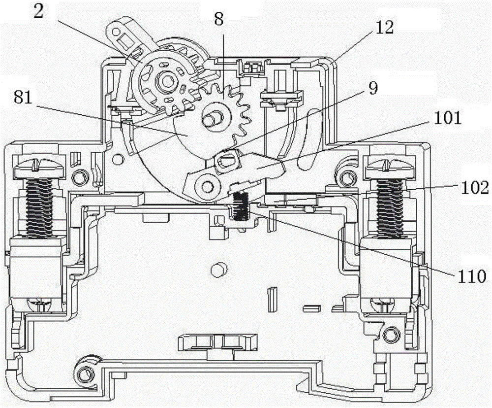
[0067] Such as figure 1 , figure 2 Shown is a specific embodiment of the contact system of the circuit breaker of the present invention,

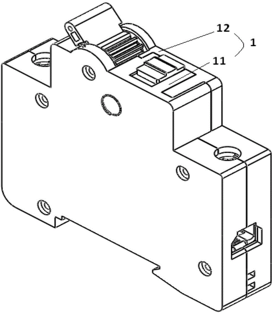
[0068] Such as figure 1 , Figure 17 and Figure 18 Shown is a specific implementation of the miniature circuit breaker of the present invention, the miniature circuit breaker includes a housing 1, and a contact system, a transmission system, a clutch device, a tripping device and a driving motor 170 arranged in the housing 1 , the transmission system includes a first transmission system and a second transmission system that drive each other, the drive motor 170 drives the first transmission system to move, and then drives the second transmission system to move, and the second transmission system drives The contact system operates to make or break the circuit breaker.

[0069] Am...


PUM


Abstract

A mini-type circuit breaker comprises a shell, and a contact system, a transmission system, a clutch device, a tripping device and a driving motor which are arranged in the shell, wherein the driving motor drives the contact system to move by the transmission system; the contact system comprises a static contact fixedly connected with the shell and a movable contact rotationally connected with the shell, and further comprises a contact support fixedly connected with the movable contact and a counter-force spring located between the shell and the movable contact; the movable contact is driven by the transmission system to be connected and disconnected with the static contact; the transmission system comprises a handle and a contact gear which are in shaft connection with the shell and are in transmission connection by a gear; the contact gear is provided with a cam driving part; the contact support abuts against the cam driving part under the elastic force effect of the counter-force spring so that the contact gear is linked with the movable contact. The technical problems of a previous circuit breaker contact system that the structure is complicated, the occupying space is large, the cost is high, the process is complicated and the service life is short are solved.

Description

technical field [0001] The invention relates to a miniature circuit breaker, which belongs to the technical field of low-voltage electrical appliances. Background technique [0002] According to the needs of my country's power supply network intelligence, the State Grid Corporation of China requires the power supply network intelligence. Therefore, it is necessary for the terminal actuator of the power supply network - the miniature circuit breaker (or miniature circuit breaker) to execute the upper-end signal and have the functions of tripping and closing. The "Technical Specifications for External Load Switches for Electric Energy Meters" issued by the State Grid Corporation of China recently stipulates that there are six types of load switches according to the number of poles, among which 1P+N is a two-pole load switch with a protective pole, requiring a small circuit breaker 2P (36mm) to realize the reclosing function, and the short-circuit breaking capacity (In) is not...

Claims


Application Information

Patent Timeline
IPC IPC(8): H01H73/04H01H71/10H01H71/02
CPCH01H71/02H01H71/10H01H73/04
Inventor 李敏徐大胜丁国辉汪泰宇陈广哲
Owner ZHEJIANG TENGEN ELECTRIC
Learn More