
Passive battery thermal management device

A management device and passive heat technology, applied in secondary batteries, battery temperature control, circuits, etc., can solve problems such as lithium analysis, difficulty in charging lithium batteries, troublesome heat dissipation of the insulation layer, etc., and achieve good heat preservation effect

Inactive Publication Date: 2015-05-06
JIANGSU HUAFU STORAGE NEW TECH DEV
View PDF4 Cites 7 Cited by
  • Summary
  • Abstract
  • Description
  • Claims
  • Application Information

AI Technical Summary

Problems solved by technology

[0002] The current thermal management methods are nothing more than fans, liquid cooling pipes, etc. These methods need external power to drive, and they need good maintenance, especially the life of the motor system is worthy of attention. In addition, thermal management generally ignores the battery pack at low temperature. The problem is that lead-acid cannot be charged at low temperature at all, and lithium battery is also very difficult to charge at low temperature. There is even a phenomenon of lithium deposition caused by low-temperature high-current charging. From the perspective of the current technical level, it is intuitive to solve the low-temperature problem. Only the method of heat preservation can be used, but how to operate it and what technical method to use are basically blank at present
Insulate the battery pack at low temperature, which can make the battery have excellent performance in the winter in the north, but the use of the insulation layer will bring huge troubles to heat dissipation in summer

Method used


Image

  • Passive battery thermal management device
  • Passive battery thermal management device

Examples


Embodiment Construction

[0015] Below in conjunction with accompanying drawing and specific embodiment, further illustrate the present invention, should be understood that these embodiments are only for illustrating the present invention and are not intended to limit the scope of the present invention, after having read the present invention, those skilled in the art will understand various aspects of the present invention Modifications in equivalent forms all fall within the scope defined by the appended claims of this application.

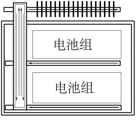
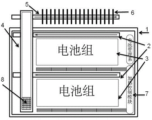
[0016] see figure 1 with figure 2 , as shown, the battery passive thermal management device of the present invention includes a battery pack, a battery box 1, a horizontal capillary heat pipe 2 inside the box, a gravity heat pipe 4, a horizontal capillary heat pipe 5 outside the box, and a heat dissipation device 6. The battery box 1 is sealed and set There is insulation. The gravity heat pipe 4 is provided with a volatile liquid working substance 8 inside, and the gr...


PUM

PropertyMeasurementUnit
Critical temperatureaaaaaaaaaa

Abstract

The invention discloses a passive battery thermal management device. The passive battery thermal management device comprises a battery pack, a battery box, a horizontal capillary heat tube in the box, a gravity heat tube, a horizontal capillary heat tube outside the box and a cooling device, wherein the battery box is sealed and is provided with a thermal preservation layer; a volatile liquid working medium is arranged in the gravity heat tube; the battery pack and the horizontal capillary heat tube in the box both are arranged in the battery box; the horizontal capillary heat tube in the box is arranged right above the battery pack, and the horizontal capillary heat tube outside the box is arranged right above the battery box; the gravity heat tube is connected with the horizontal capillary heat tube in the box and the horizontal capillary heat tube outside the box; the horizontal capillary heat tube outside the box is connected with the cooling device. The passive battery thermal management device is used for realizing the thermal management device of the battery pack by use of the gravity heat tube, namely a thermal dioxide, and the property of failure in heat conduction below a critical temperature, and can be used for solving the contradiction of the battery box between heat dissipation and thermal insulation; the battery box is sealed and is provided with the thermal preservation layer to achieve a good thermal insulation effect on the battery; as a result, maintenance is avoided in the total battery life cycle.

Description

technical field [0001] The invention belongs to the field of thermal engineering and electronic control technology, and relates to a battery passive thermal management device. Background technique [0002] The current thermal management methods are nothing more than fans, liquid cooling pipes, etc. These methods need external power to drive, and they need good maintenance, especially the life of the motor system is worthy of attention. In addition, thermal management generally ignores the battery pack at low temperature. The problem is that lead-acid cannot be charged at low temperature at all, and lithium battery is also very difficult to charge at low temperature. There is even a phenomenon of lithium deposition caused by low-temperature high-current charging. From the perspective of the current technical level, it is intuitive to solve the low-temperature problem. Only the method of heat preservation can be used, but how to operate it and what technical method to use are ...

Claims


Application Information

Patent Timeline
IPC IPC(8): H01M10/61H01M10/6568
CPCY02E60/10
Inventor 沙树勇孙庆黄毅李超周寿斌魏迪汪的华肖巍
Owner JIANGSU HUAFU STORAGE NEW TECH DEV
Features
  • Generate Ideas
  • Intellectual Property
  • Life Sciences
  • Materials
  • Tech Scout
  • Unparalleled Data Quality
  • Higher Quality Content
  • 60% Fewer Hallucinations
Learn More