A Graded Ridge Waveguide Distributed Feedback Laser with High Single-Mode Yield

A distributed feedback and distributed feedback technology, applied in the field of lasers, can solve the problems of long laser cavity, high threshold, low diffraction efficiency of second-order grating, etc., and achieve the effect of improving single-mode yield and solving low yield.

Active Publication Date: 2018-03-27
HUAZHONG UNIV OF SCI & TECH
View PDF1 Cites 0 Cited by
  • Summary
  • Abstract
  • Description
  • Claims
  • Application Information

AI Technical Summary

Problems solved by technology

Although the second-order grating DFB-LD can achieve the single longitudinal mode output of the laser, the diffraction efficiency of the second-order grating is very low, resulting in a long cavity length and a high threshold of the laser.

Method used


Image

  • A Graded Ridge Waveguide Distributed Feedback Laser with High Single-Mode Yield
  • A Graded Ridge Waveguide Distributed Feedback Laser with High Single-Mode Yield
  • A Graded Ridge Waveguide Distributed Feedback Laser with High Single-Mode Yield

Examples


Embodiment 1

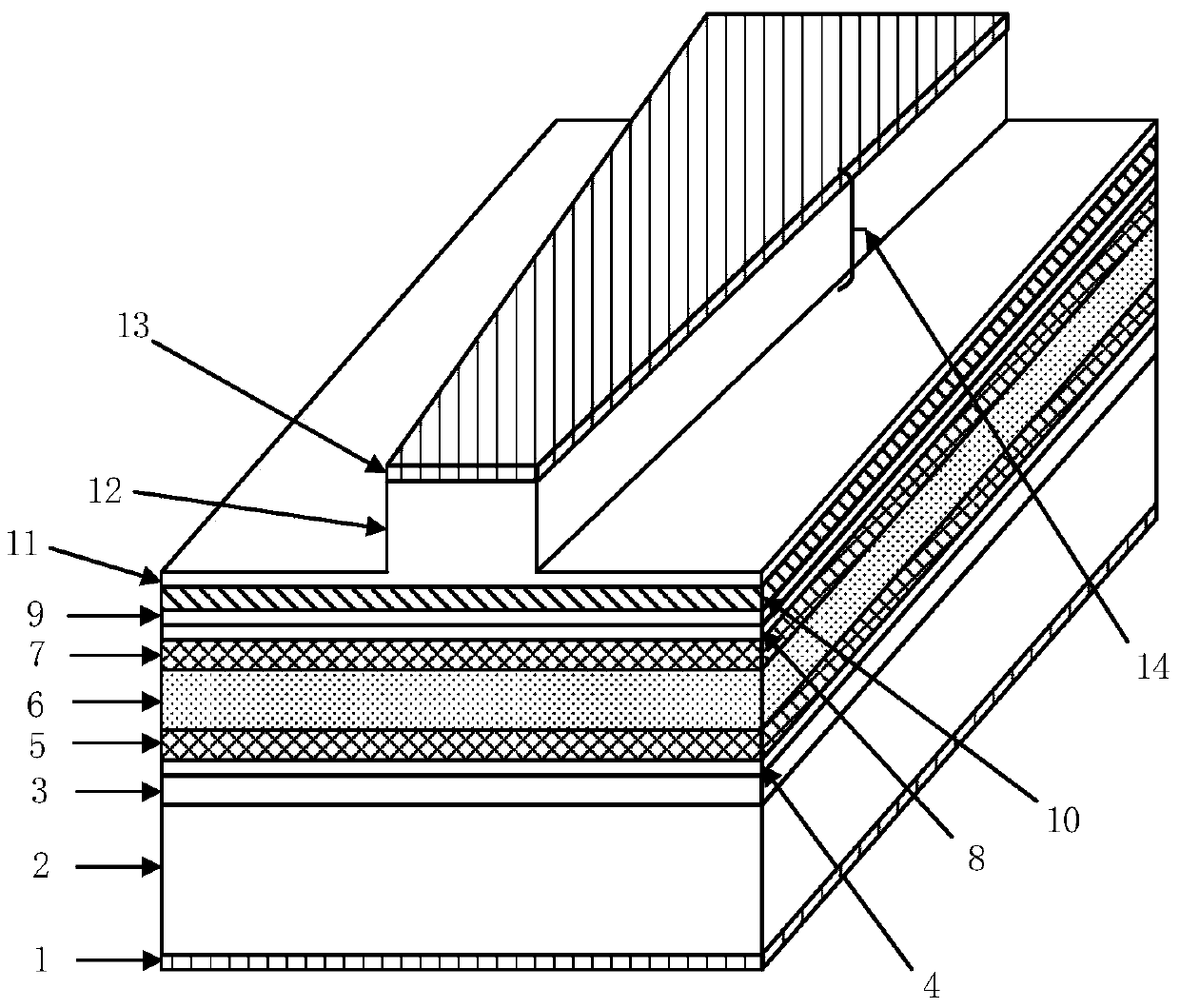
[0059] figure 1 It is a schematic structural diagram of an AlGaInAs / InP DFB semiconductor laser with an operating wavelength of 1310 nm. The laser has a resonator, and the resonator includes from bottom to top: substrate, buffer layer, first barrier layer, first separate confinement layer, quantum well active region, second separate confinement layer, second barrier layer, second A spacer layer and a second spacer layer; a grating layer in which the Bragg grating is located between the first spacer layer and the second spacer layer. The resonant cavity has a laser output end face, and the cavity length direction of the resonant cavity is perpendicular to the laser output end face.

[0060] figure 1 Among them, 1 and 13 are the contact layer, which is used to contact the metal of the electrode layer to reduce the resistance of the electrical connection, etc. The material of the contact layer is In 0.53 Ga 0.47 As, the thickness of the contact layer is 200nm; the contact lay...

Embodiment 2

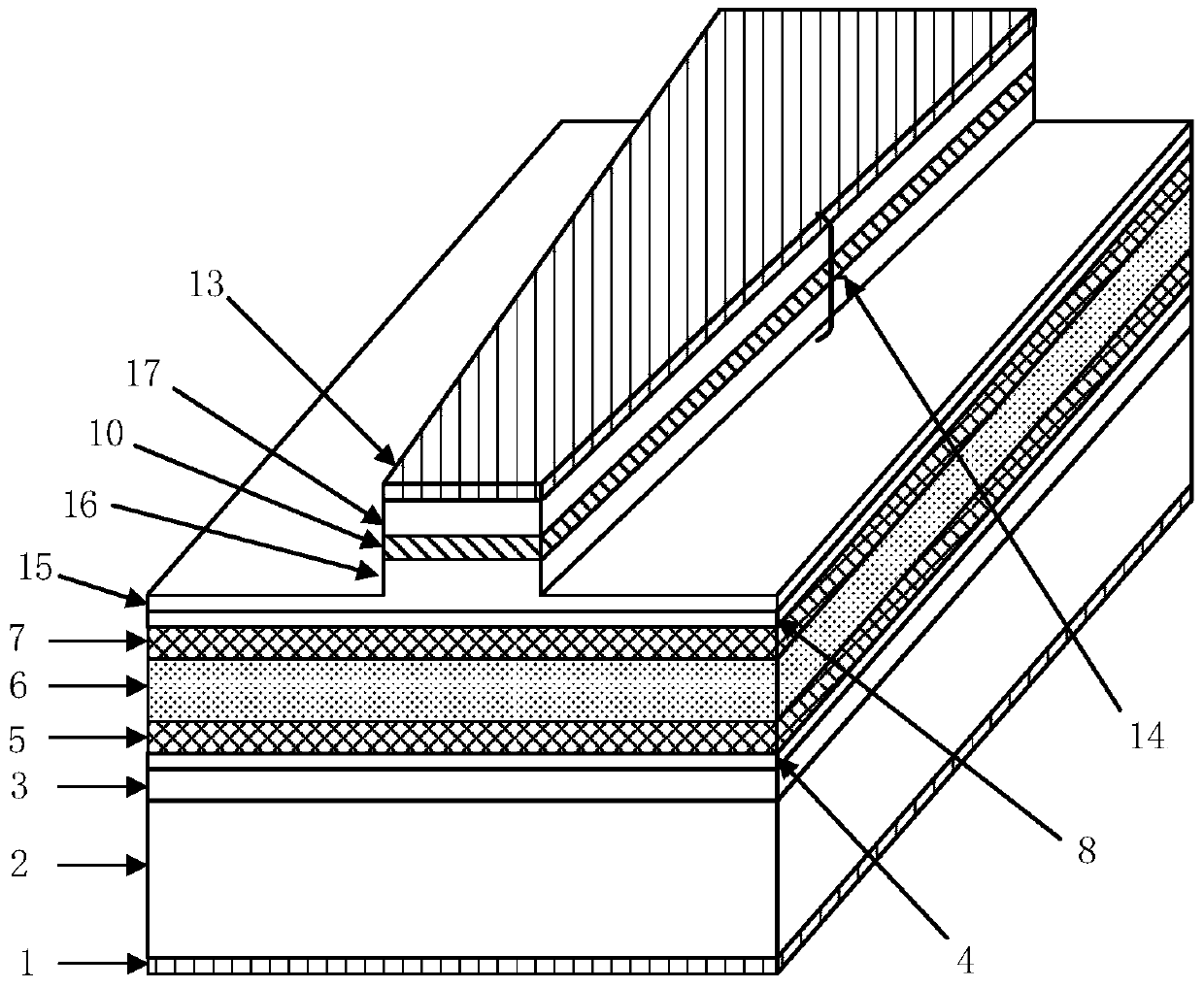
[0068] image 3 It is a schematic diagram of the structure of the 1310nm AlGaInAs / InP DFB semiconductor laser with the grating layer in the ridge, 1 and 13 in the figure are the contact layer; 2 is the substrate; 3 is the buffer layer, the material is InP, and the thickness is 500nm; are the first and second barrier layers, and the material is In 0.52 Al 0.48 As, with a thickness of 50nm; 5 and 7 are the first and second confinement layers respectively, the material is InAlGaAs, and their thickness is 100nm; 6 is the quantum well active region, which is composed of 8 well layers and 9 barrier layers cross-stacked , the material of each well layer is In 0.69 Al 0.16 Ga 0.15 As, the thickness is 5.5nm, and the material of each barrier is In 0.52 Al 0.35 Ga 0.13 As, the thickness is 9nm; 9 is the spacer layer; 10 is the grating layer, and its material is In 0.79 Ga 0.21 As 0.46 P 0.54 , the thickness is 30nm, the grating period is 204.7nm, the material is InP, and the ...


PUM


Abstract

A distributed feedback laser with high single-mode yield, including a laser resonator and a Bragg grating; the Bragg grating is a chirped grating or an equivalent chirped grating, and is located in a resonant cavity, and its equivalent refractive index is along the length of the resonant cavity. The direction is changed; the mode gain of the laser changes along the length direction of the resonant cavity; the laser outputs a single longitudinal mode. Because the present invention adopts the chirped grating or equivalent chirped grating, the mode gain of the laser is changed along the direction of the cavity length at the same time, and by coating the high reflection film and the anti-reflection film on the two ends of the laser respectively, the Bragg resistance of the laser can be improved. With the specified side, that is, the probability of laser lasing on the blue side or the red side, so as to improve the single-mode yield of the laser. The technical scheme of the invention can effectively solve the problem of low single-mode yield of the existing DFB laser, and the manufacturing process of the DFB semiconductor laser is almost the same as that of the traditional ridge waveguide DFB laser, so the manufacturing cost is equivalent.

Description

technical field [0001] The invention belongs to the field of lasers, and more specifically relates to a distributed feedback laser with high single-mode yield. Background technique [0002] With the rapid development of optical communication technology, the demand for semiconductor lasers is increasing day by day. Since the distributed feedback semiconductor laser (DFB-LD) can suppress mode hopping in a wider operating temperature and operating current range and ensure a single longitudinal mode output, it is widely used in the field of optical communication. [0003] The general DFB semiconductor laser uses a uniform grating, and its feedback method is mainly generated by using the periodic change of the refractive index in the grating, that is, index-coupling. In the ideal case where the reflectance of the end face is 0, there are two degenerate longitudinal modes in this laser, and the two longitudinal modes are symmetrically distributed on both sides of the Bragg wavele...

Claims


Application Information

Patent Timeline
Patent Type & Authority Patents(China)
IPC IPC(8): H01S5/22
Inventor 李洵奚燕萍柯程鲍士伟黄卫平
Owner HUAZHONG UNIV OF SCI & TECH
Why Eureka
Try Eureka