
A pumped storage system based on light direct current transmission

A light direct current transmission and pumped storage technology, which is applied in the direction of electric energy storage system, electrical components, AC network load balancing, etc., to achieve stable voltage, stable power angle, and flexible control

Active Publication Date: 2017-02-22
STATE GRID CORP OF CHINA +1
View PDF6 Cites 0 Cited by
  • Summary
  • Abstract
  • Description
  • Claims
  • Application Information

AI Technical Summary

Problems solved by technology

[0006] Aiming at the deficiencies existing in the existing pumped storage power station, the present invention can easily control the active and reactive power by using the light direct current transmission method. When the motor is running in the working condition, it can be easily realized by providing active power to the motor through the control system. Control and adjust the power of the motor, and use the light direct current method to control the shutdown of the current. This function can replace the function of the GCB switch at the generator outlet

Method used


Image

  • A pumped storage system based on light direct current transmission
  • A pumped storage system based on light direct current transmission

Examples


Embodiment Construction

[0017] The technical means adopted by the present invention to achieve the intended invention purpose are further described below in conjunction with the drawings and preferred embodiments of the present invention.

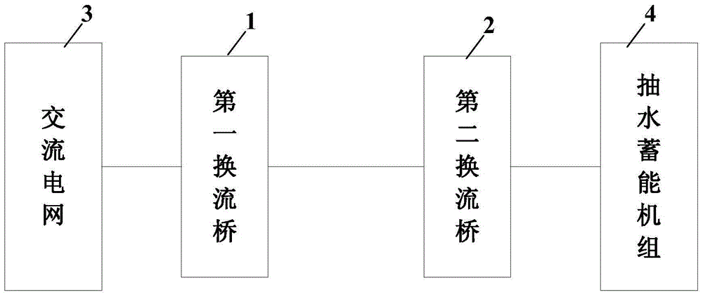
[0018] figure 1 It is a schematic structural diagram of a pumped storage system based on light DC transmission according to an embodiment of the present invention. Such as figure 1 As shown, the system includes: a first converter bridge 1, a second converter bridge 2, an AC grid 3, and a pumped storage unit 4; the first converter bridge 1 is connected to the AC grid 3, and is connected to the second converter bridge through a DC cable. The converter bridge 2, the second converter bridge 2 is connected to the pumped storage unit 4; wherein,

[0019] When pumping water, the first converter bridge 1 rectifies the AC power of the AC grid 3 into DC power, and transmits it to the second converter bridge 2 through a DC cable, and the second converter bridge 2 inverts t...


PUM


Abstract

The invention discloses a light-duty direct-current transmission based water pumping energy storage system. The system comprises a first converter bridge, a second converter bridge, an alternating-current power grid and a water pumping energy storage unit. The first converter bridge is connected to the alternating-current power grid and is connected with the second converter bridge through an alternating-current cable, and the second converter bridge is connected to the water pumping energy storage unit. When water pumping working condition is performed, the first converter bridge rectifies the alternating current of the alternating-current power grid into direct current and transmits the direct current to the second converter bridge through a direct-current cable, the second converter bridge inverts the direct current into alternating current to be transmitted to the water pumping energy storage unit to perform water pumping. When power generating working condition is performed, the water pumping energy storage unit is utilized to generate power, the second converter bridge rectifies the alternating current generated by the water pumping energy storage unit into direct current and transmits the direct current to the first converter bridge through a direct-current cable, and the first converter bridge inverts the direct current into alternating current to be transmitted to the alternating-current power grid.

Description

technical field [0001] The invention relates to the field of hydropower, in particular to a pumped water storage system based on light DC transmission. Background technique [0002] The pumped storage generator / motor unit is a two-way reversible water turbine unit. When the power grid load is too large, in order to ensure the power quality, the power generation mode is adopted. It has the same function as the traditional conventional water turbine-generator unit. , instead of pumping water, as a motor, pumping the water from the lower reservoir to the upper reservoir, and converting it into potential energy storage. [0003] The unit wiring of the traditional pumped storage unit is to install a GCB (generator circuit breaker) switch at the outlet of the generator / generator unit, that is, the generator outlet circuit breaker, which is used for synchronous grid connection and accident tripping. After boosted by the main transformer, it will run in parallel with the system gri...

Claims


Application Information

Patent Timeline
Patent Type & Authority Patents(China)
IPC IPC(8): H02J3/28
CPCH02J3/28H02J15/003Y02E60/16
Inventor 李红伟姜海山闫顺康陈毅航
Owner STATE GRID CORP OF CHINA
Learn More