Permanent magnetic speed regulating device without iron loss

A permanent magnet speed governor, iron loss technology, applied in the direction of electromechanical devices, electromechanical transmission devices, electrical components, etc., can solve the inconvenient transient response mechanical direct protection measures, extend the length of the shaft and increase the shaft weight, Displacement adjustable range is small and other problems, to achieve strong ability to contaminate or corrode, improve transmission efficiency, and improve the effect of heat dissipation efficiency

Active Publication Date: 2015-05-06
西安巨舟电子设备有限公司
View PDF14 Cites 3 Cited by
  • Summary
  • Abstract
  • Description
  • Claims
  • Application Information

AI Technical Summary

Problems solved by technology

[0006] In addition, the above-mentioned permanent magnet governor also has deficiencies in the design of the structure
Typically, Chinese Patent Announcement No. CN1140042C issued on February 25, 2004 discloses an adjustable magnetic coupler, the adjustment mechanism of which is a cylindrical end face cam mechanism, and its structure has the following defects: first, A long connecting rod mechanism perpendicular to the axis of the main shaft is required to be connected between the on-axis unit and the fixed unit, the adjustment accuracy is low, and the floor space is large; secondly, two sets of angular contact bearings are required, which is The length of the extension shaft and the increase in the axle load are relatively large; third, the adjustable range of displacement is small, the overall structure is complex, and the production cost is high; fourth, more importantly, the adjustment mechanism based on this structure is not easy to adopt instantaneous Mechanical direct protective measures with dynamic response

Method used


Image

  • Permanent magnetic speed regulating device without iron loss
  • Permanent magnetic speed regulating device without iron loss
  • Permanent magnetic speed regulating device without iron loss

Examples


Embodiment Construction

[0048] The present invention will be described in further detail below in conjunction with the accompanying drawings.

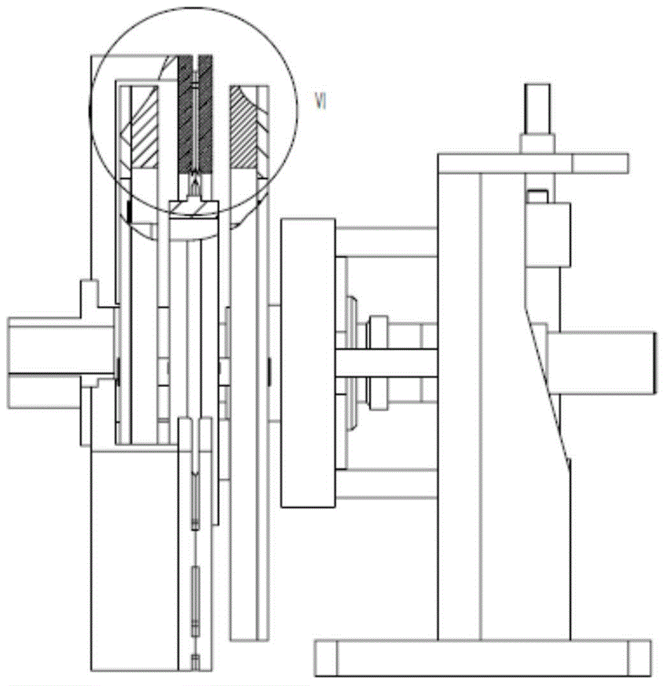
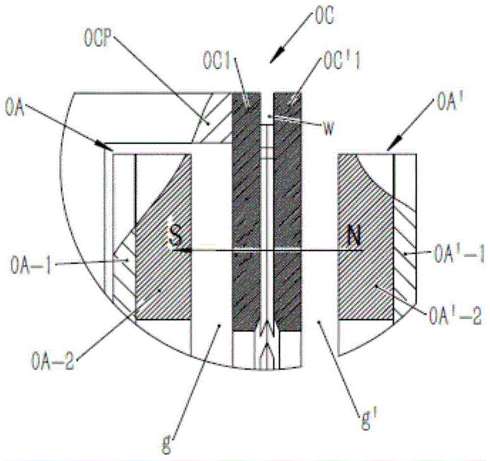
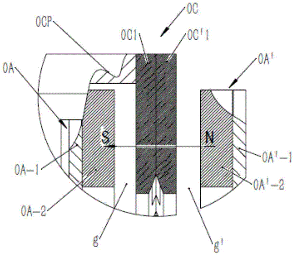
[0049] see Figure 1 to Figure 1 As shown in 0, a non-iron loss permanent magnet governor device of the present invention includes a coaxially arranged auxiliary shaft (not shown) and an extended main shaft 0; the extended main shaft 0 is provided with a permanent magnet rotor, and the permanent magnet rotor includes a component The first permanent magnet rotor disc 0A and the second permanent magnet rotor disc 0A' are paired and arranged in parallel on the extended main shaft 0; the conductor rotor base plate 0CP is fixed on the secondary shaft, and the conductor rotor base plate 0CP is fixed with a conductor rotor 0C, The conductor rotor is located between the first permanent magnet rotor disc 0A and the second permanent magnet rotor disc 0A'. There is a gap g between one side of the conductor rotor and the first permanent magnet rotor disc 0A, and the othe...


PUM


Abstract

The invention discloses a permanent magnetic speed regulating device without iron loss. The device comprises an auxiliary shaft and an extending spindle which are arranged coaxially; the extending spindle is provided with a permanent magnetic rotor; the permanent magnetic rotor comprises a first permanent magnetic rotor disc and a second permanent magnetic rotor disc which are arranged on the extending spindle in a pair parallelly; a conductor rotor base disc is fixed to the auxiliary shaft, and a conductor rotor is fixed to the conductor rotor base disc and is located between the first permanent magnetic rotor disc and the second permanent magnetic rotor disc at internal; permanent magnet groups are arranged on one opposite sides of the first permanent magnetic rotor disc and second permanent magnetic rotor disc; the device further comprises a drive mechanism driving the first permanent magnetic rotor disc and the second permanent magnetic rotor disc to move oppositely and synchronously along the axis of the extending spindle. The device has the advantages that the magnetic paths are optimized, ferromagnetic material of an outer magnetic path chain is omitted, iron loss of the product is avoided during operation, the transmitting efficiency of the torque can be improved, and the temperature rising is reduced.

Description

【Technical field】 [0001] The invention belongs to the technical field of mechanical transmission, in particular to a non-iron loss permanent magnet governor device. 【Background technique】 [0002] The basic principle of the existing permanent magnetic coupling device is to use the relative motion between the conductor rotor and the permanent magnet rotor to induce a vortex magnetic field on the conductor rotor. . Using this mechanism, the power is transmitted from the power side to the load side in a non-contact manner. Its theoretical basis is classic and well-known, and the methods or prototypes for principle verification are diverse and simple, but there are still few mature engineering applications. [0003] The first type of permanent magnet governor is disc-shaped, which adjusts the distance between the conductor rotor and the permanent magnet rotor, that is, adjusts the size of the air gap. The larger the air gap, the smaller the transmitted torque and the larger th...

Claims


Application Information

Patent Timeline
IPC IPC(8): H02K51/00
Inventor 马小安
Owner 西安巨舟电子设备有限公司
Why Eureka
Try Eureka