Disaster recovery method and equipment

A technology of equipment and network equipment, which is applied in the field of communication, and can solve problems such as business data cannot be allocated, business interruption, business data cannot be transmitted normally, etc.

Active Publication Date: 2015-05-06
HUAWEI TECH CO LTD
View PDF5 Cites 7 Cited by
  • Summary
  • Abstract
  • Description
  • Claims
  • Application Information

AI Technical Summary

Problems solved by technology

[0004] However, when the BSC or RNC connected to the RSG fails, the service data received by the base station connected to the BSC or RNC cannot be distributed to the transmission network, and the service data cannot be transmitted normally, resulting in the failure of the service that the BSC or RNC is responsible for. all interrupted

Method used


Image

  • Disaster recovery method and equipment
  • Disaster recovery method and equipment
  • Disaster recovery method and equipment

Examples


Embodiment Construction

[0078] The embodiments of the present invention provide disaster recovery methods and equipment. In order to make the purpose, technical solutions and advantages of the embodiments of the present invention more clear, the technical solutions in the embodiments of the present invention will be clarified below in conjunction with the accompanying drawings in the embodiments of the present invention described.

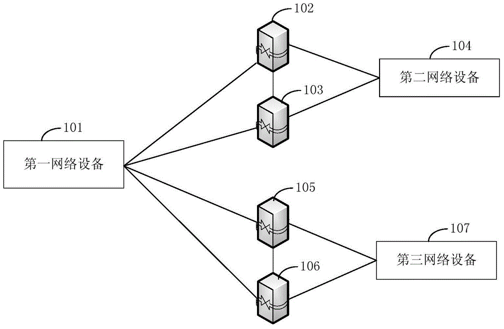
[0079] figure 1 It is a schematic structural diagram of a network system implementing a disaster recovery method provided by an embodiment of the present invention. The first network device 101 is respectively deployed to virtual links (Pseudo Wire, PW) of four network transit devices. The PW between the first network device 101 and the first active network transfer device 102 is the first active PW, and the PW between the first network device 101 and the first backup network transfer device 103 is the first backup PW, the first active PW and the first standby PW belong ...


PUM


Abstract

The embodiment of the invention provides a disaster recovery method and disaster recovery equipment. The disaster recovery method comprises the following steps: first network equipment is used for monitoring faults of second network equipment; the first network equipment is used for finding a standby PW set corresponding to a primary virtual link PW set from the pre-configured information; the first network equipment switches a state of a second primary PW in the standby PW set to active-active from inactive-active, and switches the state of the second standby PW to active-inactive from inactive-inactive; the first network equipment utilizes the standby PW set to send the received business data to network transfer equipment connected with the third network equipment; when the second network equipment has faults, the first network equipment utilizes the standby PW set to send the received business data to the third network equipment which is taken as standby equipment of the second network equipment, thereby realizing business data normal transmission charged by the second network equipment.

Description

technical field [0001] The present invention relates to the field of communication technology, in particular to a method and equipment. Background technique [0002] In the IP radio access network (IP Radio Access Network, IPRAN) low-speed card service data transmission system, one end of the base station side gateway (Cell Site Gateway, CSG) is connected to the base station, and the other end is dual-homed to two wireless service gateways ( Radio Service Gateway, RSG), and two RSGs are connected to the same base station controller (Base Station Controller, BSC) or radio network controller (Radio Network Controller, RNC). [0003] The CSGs are respectively deployed to the virtual links (Pseudo Wire, PW) of two RSGs, one of which is the active PW and the other is the standby PW, and an inter-chassis backup virtual link (Inter- Chassis Backup PW, ICB PW), when the active PW fails, switch to the standby PW. The base station receives the service data sent by the terminal, and ...

Claims


Application Information

Patent Timeline
Patent Type & Authority Applications(China)
IPC IPC(8): H04W24/04
CPCH04W24/04
Inventor 张耀坤孙春霞
Owner HUAWEI TECH CO LTD
Why Eureka
Try Eureka