
Dual-winding single-stage primary feedback LED (Light Emitting Diode) lamp drive circuit

A technology of LED lamp and primary side feedback, applied in the direction of electric lamp circuit layout, electric light source, electrical components, etc., can solve the problems of complex manufacturing process and high cost

Active Publication Date: 2015-05-06
SHENZHEN WINSEMI MICROELECTRONICS
View PDF9 Cites 22 Cited by
  • Summary
  • Abstract
  • Description
  • Claims
  • Application Information

AI Technical Summary

Problems solved by technology

[0005] The technical problem to be solved by the present invention is to provide a dual-winding single-stage primary-side feedback LED lamp drive circuit to solve the problem that the LED lamp drive circuit needs a line voltage detection circuit and the transformer needs three windings in the prior art. complex, costly problems

Method used


Image

  • Dual-winding single-stage primary feedback LED (Light Emitting Diode) lamp drive circuit
  • Dual-winding single-stage primary feedback LED (Light Emitting Diode) lamp drive circuit
  • Dual-winding single-stage primary feedback LED (Light Emitting Diode) lamp drive circuit

Examples


Embodiment Construction

[0022] The present invention will be described in detail below in conjunction with the accompanying drawings and specific embodiments.

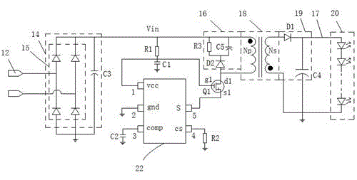
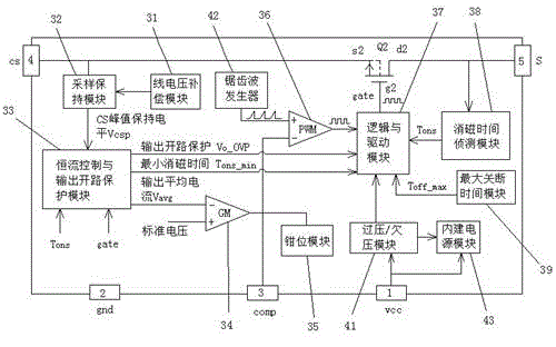
[0023] see figure 2, the present invention provides a double-winding single-stage primary-side feedback LED lamp drive circuit, including: AC input terminal 12, first rectification and filtering module 14, absorption circuit 16, transformer 18, second rectification and filtering module 19, LED lamp The access terminal 17, the first power transistor Q1, the LED driver chip 22, the first resistor R1, the second resistor R2, the first capacitor C1 and the second capacitor C2, the LED driver chip 22 has first to fifth pins 1, 2, 3, 4, 5 (vcc, gnd, comp, cs, S), the first rectification and filtering module 14 is respectively connected to the AC input terminal 12, one end of the first resistor R1, the absorption circuit 16, and the transformer 18 Electrically connected, the other end of the first resistor R1 is respectively electrically connected...


PUM


Abstract

The invention provides a dual-winding single-stage primary feedback LED (Light Emitting Diode) lamp drive circuit. An LED drive chip of a source drive technology is adopted, and degaussing time Tons (namely secondary side turn-on time) is indirectly detected through parasitic capacitors at source and drain of an external first power transistor; an extremely high power factor is also realized through a control method of fixed primary side turn-on time Tonp to relieve power grid pressure; open-circuit protection of an output LED is realized through a correlation technique of the primary side turn-on time and a primary side current peak value; besides, since the LED drive chip has extremely low working current, power can be directly supplied by line voltage through a first resistor; thus auxiliary winding required for detecting the power supply and degaussing time and output voltage of the LED drive chip of the existing primary side feedback LED drive circuit is omitted; the transformer is only provided with a primary side winding and a secondary side winding, so the manufacturing process flow of the transformer is simplified, and the cost is further reduced.

Description

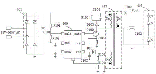
technical field [0001] The invention relates to the technical field of switching power supplies, in particular to a double-winding single-stage primary-side feedback LED lamp driving circuit. Background technique [0002] With people's requirements for environmental protection, energy saving and high efficiency, LED lighting has made rapid progress in recent years and achieved leapfrog development. In order to ease the pressure on the power grid and reduce costs, primary side feedback (PSR) LED driver chips with single-stage power factor correction (PFC) have begun to appear on the market in the last two years. [0003] see figure 1 , which is an existing single-stage power factor correction primary-side feedback LED drive circuit, the primary-side feedback LED drive circuit includes: a control chip 400, a transformer 413, a power transistor Q100, a rectifier bridge 401, a line voltage detection resistor R101 and R102, high voltage capacitor C101, auxiliary side rectifier ...

Claims


Application Information

Patent Timeline
IPC IPC(8): H05B37/02H02M3/335H02M1/42
CPCY02B20/40Y02B70/10
Inventor 宋利军许煌樟
Owner SHENZHEN WINSEMI MICROELECTRONICS
Learn More