Clothes dryer

A technology for dryers and clothes, applied to other washing machines, household clothes dryers, washing machines with containers, etc., can solve problems such as poor insulation, reduced function of blower and heat exchanger, and reduced performance of lint removal, so as to avoid electric leakage risk effect

Active Publication Date: 2015-05-06
PANASONIC INTELLECTUAL PROPERTY MANAGEMENT CO LTD
View PDF7 Cites 13 Cited by
  • Summary
  • Abstract
  • Description
  • Claims
  • Application Information

AI Technical Summary

Problems solved by technology

[0002] Conventionally, in clothes dryers equipped with heat pump devices, there has been the following problem: lint generated from fiber products such as clothes is mixed into the drying air, adheres to and accumulates on the blower and heat exchanger installed in the circulating air duct, and makes the blower and the function of the heat exchanger, etc. is reduced
[0011] In the above-mentioned conventional technology, the heat exchanger is cleaned with tap water, so if the compressor 154 is insulated poorly when the tap water comes into contact with the heat exchanger, electricity may leak to the water pipe through the tap water.
Therefore, it is necessary to temporarily store water, etc. and cut off the tap water, but this has the following problems: the pressure of the tap water sprayed to the heat exchanger is lowered, and the lint removal performance is lowered

Method used


Image

  • Clothes dryer
  • Clothes dryer
  • Clothes dryer

Examples


no. 1 approach

[0027] First, a first embodiment of the present invention will be described.

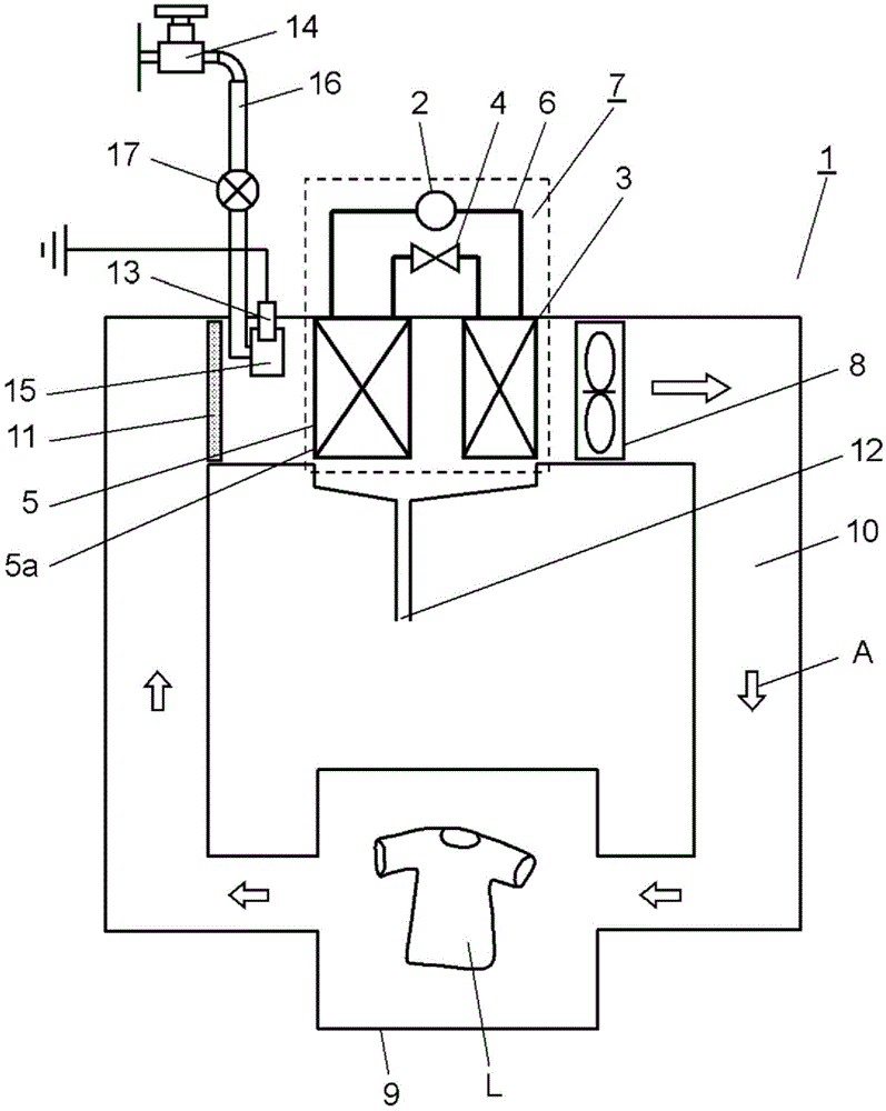
[0028] figure 1 It is a figure which shows the structure of the clothes dryer 1 which concerns on 1st Embodiment of this invention.

[0029] Clothes dryer 1 has heat pump device 7 for dehumidifying and heating drying air. The heat pump device 7 includes: a compressor 2, which compresses the refrigerant; a condenser 3, which releases the heat of the compressed high-temperature and high-pressure refrigerant; The decompressed capillary tube structure; and the evaporator 5 which uses the decompressed and low-pressure refrigerant to take heat from the surroundings. The heat pump device 7 is obtained by connecting the compressor 2 , the condenser 3 , the throttle unit 4 , and the evaporator 5 through the piping 6 so that the refrigerant circulates.

[0030] The condenser 3 and the evaporator 5 are constituted by metal finned tube heat exchangers. The pipe 6 through which the refrigerant flows is form...

no. 2 approach

[0054] Next, a second embodiment of the present invention will be described.

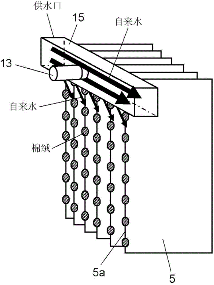
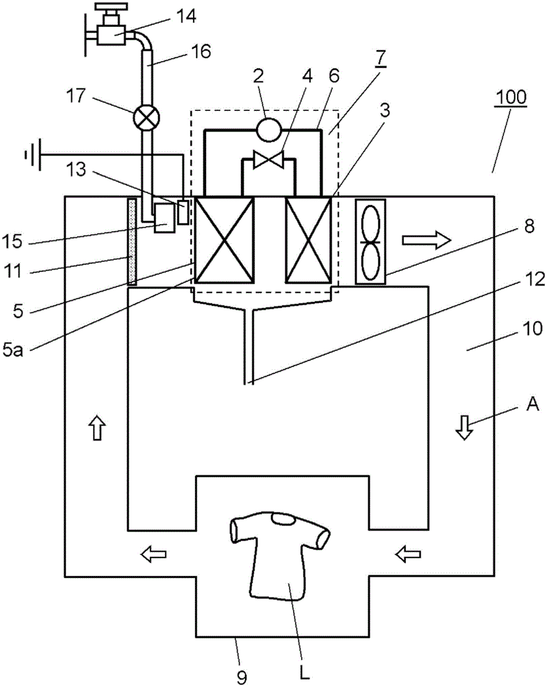
[0055] image 3 It is a figure which shows the structure of the clothes dryer 100 which concerns on the 2nd Embodiment of this invention. in addition, Figure 4 It is a schematic diagram of the vicinity of the evaporator 5 during the lint removal process of the laundry dryer 100 according to the second embodiment of the present invention.

[0056] The difference between the clothes dryer 100 of the present embodiment and the clothes dryer 1 of the first embodiment is the position where the grounding portion 13 is disposed.

[0057] In the clothes dryer 100 of the present embodiment, the ground portion 13 is arranged between the discharge portion 15 and the evaporator 5 . In this way, at least a part of the washing water sprayed from spray portion 15 is sprayed to contact portion 13 . The other configurations are the same as those described in the first embodiment, and the same reference numerals...


PUM


Abstract

A clothes dryer (1) is provided with: a heat pump device (7) formed by connecting a compressor (2), a condenser (3), a throttle section (4), and an evaporator (5) by a pipe path (6) so that a refrigerant circulates therethrough; a drying chamber (9) for receiving an object to be dried; and an air flow path (10) for conducting drying air to the drying chamber (9). The clothes dryer (1) is also provided with: a blower (8) for delivering the drying air to the drying chamber (9); a discharge section (15) disposed upwind of the evaporator (5) and discharging cleaning water toward the evaporator (5); a water supply path (16) for supplying the cleaning water to the discharge section (15); and a ground section (13) for discharging electrical charges within the heat pump device (7) to the ground. The ground section (13) is provided so as to be in contact with at least a part of the cleaning water discharged from the discharge section (15).

Description

technical field [0001] The present invention relates to a clothes dryer for drying fiber products such as clothes. Background technique [0002] Conventionally, in clothes dryers equipped with heat pump devices, there has been the following problem: lint generated from fiber products such as clothes is mixed into the drying air, adheres to and accumulates on the blower and heat exchanger installed in the circulating air duct, and makes the blower and the function of the heat exchanger etc. is degraded. Therefore, a lint filter for trapping lint from the drying air is installed in the circulation duct. [0003] However, since it is necessary to ensure a fixed amount of the drying air flowing through the circulation duct, it is difficult to completely remove lint from the drying air passing through the lint filter. Therefore, there is a problem that the lint passing through the lint filter adheres to the heat exchanger. Therefore, it is considered to wash the lint adhering ...

Claims


Application Information

Patent Timeline
Patent Type & Authority Applications(China)
IPC IPC(8): D06F58/02D06F25/00D06F39/10
CPCD06F58/206D06F58/22
Inventor 中井厚仁桐山博之河合雅弘寺井谦治
Owner PANASONIC INTELLECTUAL PROPERTY MANAGEMENT CO LTD
Why Eureka
Try Eureka