
Diseased part development and projection navigation device

A navigation device and projection technology, applied in medical science, using light for diagnosis, using fluorescence emission for analysis, etc., can solve problems such as difficulties, poor image accuracy, and increased image processing, so as to improve accuracy and success rate , strong contrast, avoiding the effect of influence

Inactive Publication Date: 2015-05-13
合肥新迈美克医疗科技有限公司
View PDF9 Cites 12 Cited by
  • Summary
  • Abstract
  • Description
  • Claims
  • Application Information

AI Technical Summary

Problems solved by technology

Although this method can present the information required for the operation in front of the doctor, the image seen by the doctor is displayed separately from the actual lesion of the patient, which requires the doctor to constantly switch the field of view during the operation, resulting in the doctor being unable to remove the lesion in the process of removing the lesion. operate precisely
At the same time, because the doctor needs to constantly switch the viewing angle to obtain the information provided by the image, it brings great inconvenience to the doctor during the operation.
[0005] Some people also proposed the method of projecting the processed medical image to the corresponding operation area, but this will cause the projected image to be collected by the acquisition device again, which will increase the difficulty of image processing at the next moment and introduce unnecessary Background Image and Noise
As a result, the accuracy of the collected and projected images deteriorates, increasing the uncertainty of the operation

Method used


Image

  • Diseased part development and projection navigation device

Examples


Embodiment Construction

[0026] In order to make the purpose, technical solution and advantages of the present invention clearer, the technical solution of the present invention will be clearly and completely described below in conjunction with specific embodiments of the present invention and corresponding drawings.

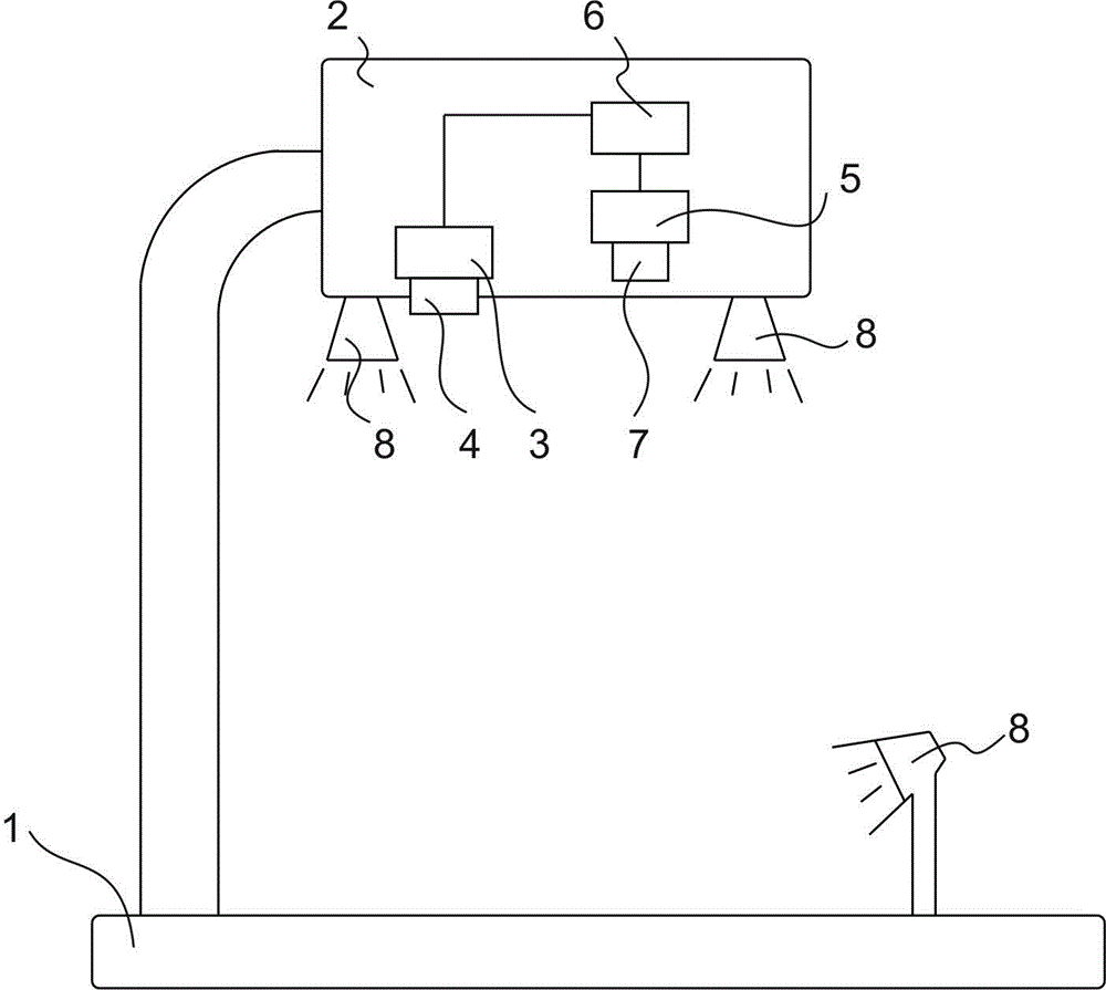
[0027] refer to figure 1 , in one embodiment of the present invention, lesion imaging projection navigation device comprises bracket, is provided with image acquisition part 5, projection part 3 and a plurality of excitation light sources 8 on the bracket, image acquisition part 5 is connected with projection part 3, and projection part A projection modulation device 4 and a projection image registration system are provided on it.

[0028] The image acquisition component 5 may be a CCD, a CMOS camera or other image acquisition components.

[0029] In one embodiment of the present invention, a CCD camera with strong near-infrared sensitivity is selected as the image acquisition componen...


PUM


Abstract

The invention discloses a diseased part development and projection navigation device comprising a support. An image collecting component, a projection component and multiple exciting light sources are arranged on the support. The image collecting component is connected with the projection component. The projection component is provided with a projection modulation device and a projection image alignment system. According to the diseased part development and projection navigation device, image collection and image projection are controlled by the projection modulation device and the projection image alignment system in a sub-period mode to be conducted alternately, and the images projected by the projection device will not be collected by an image collecting device; in an exciting light illumination interval, the projection device projects fluorescence images to corresponding diseased part of tissue and aligns the projected images, and the projected images are captured by the naked eyes of a doctor; in this way, a surgical doctor can see the projected images, the imaged projected by the projection device are prevented from being collected by the image collecting component, the influence of the projection image and other background light on the fluorescence images is avoided, and the precision and the success rate of surgery are improved.

Description

technical field [0001] The invention relates to the technical field of medical operation auxiliary devices, in particular to a lesion imaging projection navigation device. Background technique [0002] Due to the limitation of surgical equipment, instruments and technology, traditional medical surgery relies heavily on the clinical experience of the surgeon, and different doctors have different clinical experience, which will result in different surgical accuracy and success rate. At the same time, when performing traditional medical surgery, the work intensity and workload of the surgeon are very large. [0003] In recent decades, with the development and innovation of medical imaging technology, image processing technology and other technologies, surgical operations are developing in the direction of precision, accuracy and speed. The surgical navigation system is a new type of surgical auxiliary equipment developed during this process. The basic principle of this type of...

Claims


Application Information

Patent Timeline
IPC IPC(8): A61B5/00A61B19/00
CPCA61B5/0059A61B5/0071
Inventor 邵鹏飞甘启马建民
Owner 合肥新迈美克医疗科技有限公司
Learn More