Airflow impurity separation device and manufacturing method of airflow impurity separation device

A separation device and impurity technology, which is applied in the manufacturing field of separation device, impurity separation device in airflow, and impurity separation device in airflow. It can solve problems such as blockage, poor suction, and low collection efficiency, so as to reduce the cost of use and prolong maintenance. The effect of high cycle and separation efficiency

Active Publication Date: 2015-05-13
陈美青
View PDF8 Cites 10 Cited by
  • Summary
  • Abstract
  • Description
  • Claims
  • Application Information

AI Technical Summary

Problems solved by technology

[0004] At present, most of the devices for collecting and purifying oil mist use filter screens filled with layers of overlapping fibers. In addition to consuming the original air flow and pressure of the filter screen, it is difficult to effectively separate the oil intercepted in the filter screen. Not ideal, there is a problem of low colle

Method used


Image

  • Airflow impurity separation device and manufacturing method of airflow impurity separation device
  • Airflow impurity separation device and manufacturing method of airflow impurity separation device
  • Airflow impurity separation device and manufacturing method of airflow impurity separation device

Examples


Embodiment 1

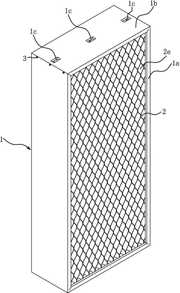
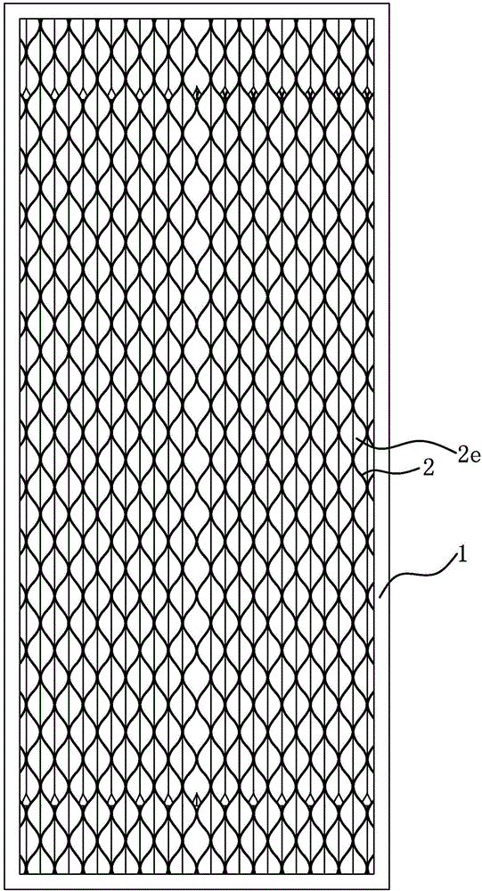
[0036] Such as Figure 1 to Figure 6 As shown, the impurity separation device in the air flow includes two layers of separation filter plates 2 and a frame 1 .

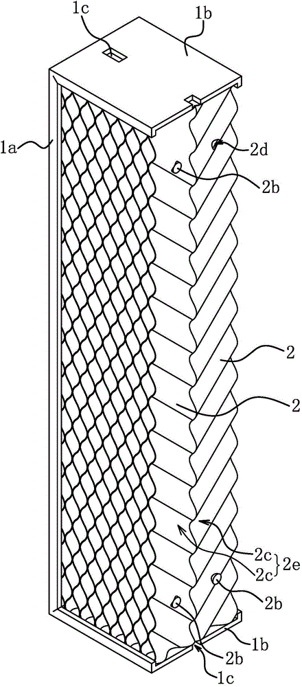
[0037] The separation filter plate 2 includes a plurality of wavy folded plates 2a and two connecting rods 2b. The folded plates 2a have multiple air passages 2a1, and the air passages 2a1 are arranged obliquely relative to the longitudinal line of the folded plates 2a. The two connecting rods 2b pass through all the folded plates 2a, and all the folded plates 2a are stacked in sequence, and the crest of one folded plate 2a abuts against the trough of the adjacent folded plate 2a; Separation channel 2c arranged obliquely relative to the plate surface. The separation channels 2c on the separation filter plate 2 face the same direction.

[0038] Two layers of separation filter plates 2 are stacked together, and the separation channels 2c on the two layers of separation filter plates 2 face opposite directions, such as...

Embodiment 2

[0047] The structure and principle of this embodiment are basically the same as that of Embodiment 1, and the basic similarities will not be redundantly described, and only the differences will be described, and the differences are as follows: Figure 7 and Figure 8 As shown, the air passage 2a1 in the folded plate 2a is V-shaped, and the corners are circular arcs with a gentle transition.

[0048] Such as Figure 9 and Figure 10 As shown, a plurality of folded plates 2a are sequentially stacked to form a layer of separation filter plate 2, and the wave crest in one folded plate 2a of the two adjacent folded plates 2a abuts against the wave trough in the adjacent folded plate 2a. The air passages 2a1 in the two adjacent folded plates 2a are arranged alternately, Figure 10 The dotted line indicates a folded plate 2a, and the solid line indicates a folded plate 2a.

[0049] The method for manufacturing the impurity separation device in the right air flow includes parts pr...


PUM


Abstract

The invention provides an airflow impurity separation device and a manufacturing method of the airflow impurity separation device, belonging to the technical field of operation, and solving the problem that the existing filter screen is easy to clog. The airflow impurity separation device comprises a frame and a plurality of folded plates arranged in the frame, wherein the folded plates are folded in a continuous wave mode to form a plurality of air channels; and a plurality of folded plates are folded to form a plurality of V-shaped separation filter holes. The airflow impurity separation device only needs to be cleaned on schedule and does not need to be replaced, and further, the use cost is reduced. The airflow impurity separation device is easy to clean, separated grease and water vapor can automatically flow out, and maintenance period is prolonged. The airflow impurity separation device is high in separation efficiency and stable in performance. The airflow impurity separation device manufactured by adopting the manufacturing method has the advantages that the number of production devices is few, the number of required processing parts is few, and production cost is low.

Description

technical field [0001] The invention belongs to the field of operation technology, and relates to a separation device, in particular to a separation device for impurities in air flow. [0002] The invention belongs to the technical field of operations, and relates to a separation device, in particular to a method for manufacturing an impurity separation device in an air stream. Background technique [0003] Environmental pollutants such as oil mist, water mist, and dust will be produced during mechanical processing. The pollutants will have adverse effects on the human respiratory system and skin health. Working in a polluted environment for a long time will increase the incidence of occupational diseases. Oil mist diffuses in the air, which will lead to failure of the circuit system and control system of the machine tool for a long time, and increase maintenance costs. To this end, it is necessary to collect and purify the pollutants. [0004] At present, most of the devi...

Claims


Application Information

Patent Timeline
IPC IPC(8): B01D46/00B01D50/00
Inventor 陈美青
Owner 陈美青
Why Eureka
Try Eureka