
High-precision synchronization self-alignment engine-driven clamp

A high-precision synchronization and automatic centering technology, applied in the field of machining, can solve the problems of long axial space occupation, inconvenient replacement of clamping jaws, small diameter opening allowance, etc., to achieve large opening size, small wear effect and easy manufacturing Effect

Inactive Publication Date: 2015-05-13
SUZHOU XIYAN MACHINERY TECH CO LTD
View PDF11 Cites 45 Cited by
  • Summary
  • Abstract
  • Description
  • Claims
  • Application Information

AI Technical Summary

Problems solved by technology

However, there are few high-precision automatic concentric fixtures that are used under conditions of great force and high load.
For example: spring collets mainly use hydraulic pull or push to convert axial force into radial force through inclined planes. They are generally suitable for rotating occasions, and occupy a long space in the axial direction. It is convenient to load and unload workpieces with large diameter changes; there are connecting rods or cam concentric mechanisms with large gaps, insufficient strength and low precision, which are not suitable for finishing machining; the form of wedge mechanism fixtures also converts or amplifies the force through the inclined plane, which is processed in this way Difficult, difficult to ensure accuracy, inconvenient to replace jaws

Method used


Image

  • High-precision synchronization self-alignment engine-driven clamp

Examples


Embodiment Construction

[0028] In order to make the object, technical solution and advantages of the present invention clearer, the present invention will be further described in detail below in conjunction with the embodiments and accompanying drawings. It should be understood that the specific embodiments described here are only used to explain the present invention, not to limit the present invention.

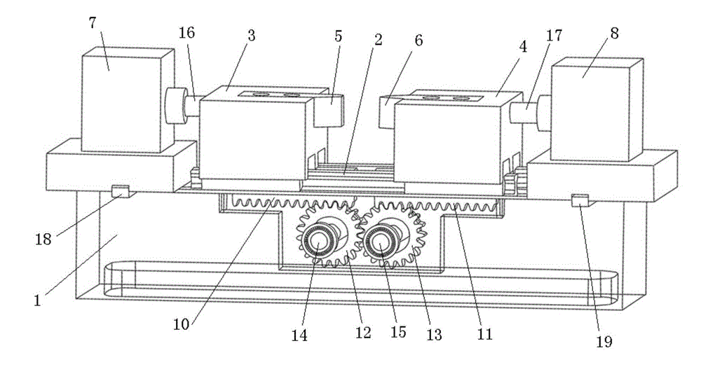
[0029] Such as figure 1 As shown, the high-precision synchronous self-centering motorized fixture of the present invention includes a clamp body 1 and two sets of rolling guide rails 2 installed side by side on the clamp body 1. In this embodiment, the clamp body 1 adopts a horizontal integral cast steel clamp body . Wherein, each set of rolling guide rails 2 is symmetrically installed with two guide rail sliders slidingly matched with it, the first pair of guide rail sliders at one end of the two sets of rolling guide rails 2 is equipped with a first thrust block 3, and the other ends of the two ...


PUM


Abstract

The invention provides a high-precision synchronization self-alignment engine-driven clamp. The high-precision synchronization self-alignment engine-driven clamp comprises a clamp body, two rolling guide rails, two pairs of guide rail sliding blocks, a first thrust block, a second thrust block, a first clamping jaw, a second clamping jaw, a first driving mechanism, a second driving mechanism, a first rack, a second rack, a first gear and a second gear, wherein the rolling guide rails are installed on the clamp body side by side, the guide rail sliding blocks are installed on the rolling guide rails, the first thrust block and the second thrust block are installed on the guide rail sliding blocks, the first clamping jaw and the second clamping jaw are installed on the first thrust block and the second thrust block respectively, the first driving mechanism and the second driving mechanism are installed on the clamp body, one end of the first driving mechanism and one end of the second driving mechanism are connected with the first thrust block and the second thrust block respectively, and the first gear and the second gear are meshed with the first rack and the second rack respectively. According to the clamp, the two meshed gears are adopted as a synchronization mechanism, and the two racks are used as a linear moving mechanism, so that the linear motion of the two racks and the rotating motion of the two gears are converted, the relative synchronous motion of the two clamping jaws can achieve clamping, and then synchronous self-alignment workpiece clamping is achieved.

Description

technical field [0001] The invention relates to the field of mechanical processing, in particular to a high-precision synchronous self-centering motorized fixture. Background technique [0002] At present, the structure of the machining centering fixture in the prior art is generally composed of collets, connecting rod mechanisms, cam mechanisms, wedge mechanisms, etc., and the fixtures are in various forms and styles. However, there are still few high-precision automatic concentric fixtures that are used under conditions of great force and high load. For example: spring collets mainly use hydraulic pull or push to convert axial force into radial force through inclined planes. They are generally suitable for rotating occasions, and occupy a long space in the axial direction. It is convenient to load and unload workpieces with large diameter changes; there are connecting rods or cam concentric mechanisms with large gaps, insufficient strength and low precision, which are not...

Claims


Application Information

Patent Timeline
IPC IPC(8): B23Q3/08
CPCB23Q3/082
Inventor 付吉艳姜洪权
Owner SUZHOU XIYAN MACHINERY TECH CO LTD
Learn More