
Automatic panel replacing and machining equipment

A technology for processing equipment and panels, which is applied in the field of panel automatic refueling processing equipment, can solve the problems of increasing the labor burden of operators, reducing the degree of automation of processing machines, and uneven allowance, so as to improve processing efficiency and processing quality, and improve processing. Efficiency and processing quality, the effect of the allowance is uniform and consistent

Active Publication Date: 2015-05-13
江西衡源智能装备股份有限公司
View PDF8 Cites 8 Cited by
  • Summary
  • Abstract
  • Description
  • Claims
  • Application Information

AI Technical Summary

Problems solved by technology

[0005] However, since the part of the glass panel or metal panel is carried out manually by the operator from the material box to the working platform, the labor burden of the operator is increased and the automation degree of the existing processing machine is reduced; At the same time, the clamping and centering of the parts of the glass panel or metal panel on the working platform is performed by the operator according to personal experience, so the neutrality of the parts of the glass panel or metal panel is poor. The parts of the glass panel or metal panel are not well centered, so that the margins left on each side of the glass panel or metal panel parts are uneven, some places are more, some places are less, which seriously affects the glass panel or metal panel. Processing efficiency and processing quality of metal panel parts
[0006] Of course, when the existing processing machine transfers other panels except the glass panel, the above-mentioned defects also exist.

Method used


Image

  • Automatic panel replacing and machining equipment
  • Automatic panel replacing and machining equipment
  • Automatic panel replacing and machining equipment

Examples


Embodiment Construction

[0031] In order to describe the technical content and structural features of the present invention in detail, further description will be given below in conjunction with the implementation and accompanying drawings.

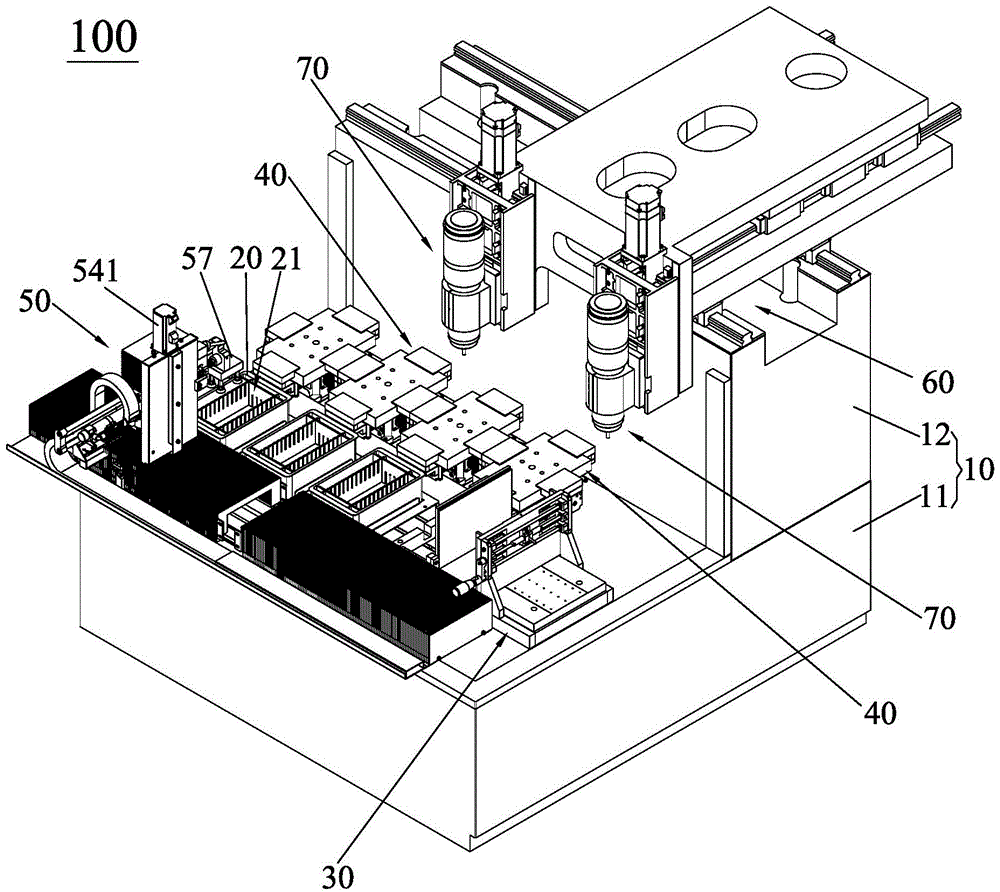
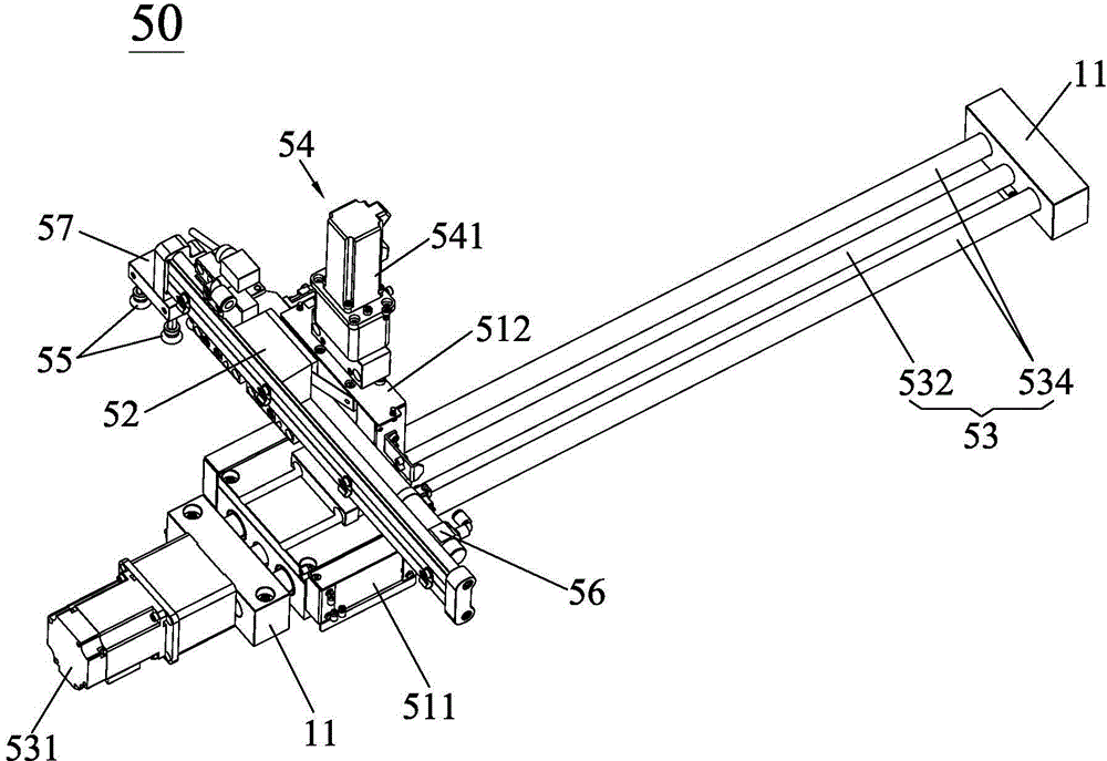
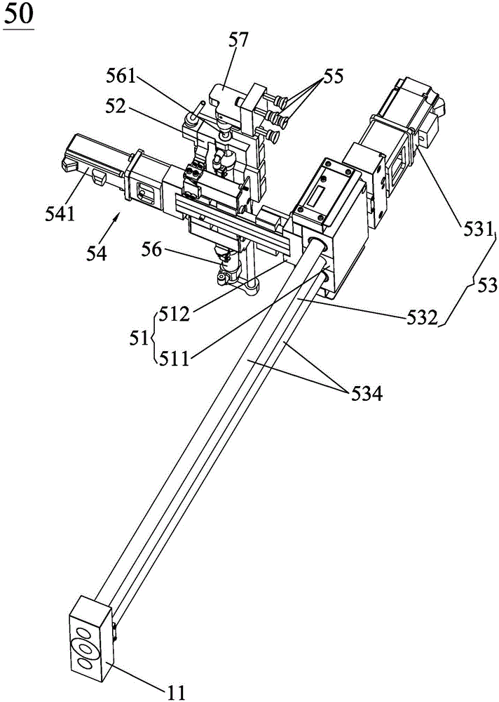
[0032] see figure 1 , the panel automatic refueling processing equipment 100 of the present invention is used for the purpose of automatically refueling and processing the panel 200 . Wherein, the panel automatic refueling processing equipment 100 of the present invention includes a frame 10 , a material box 20 , a piece-by-piece conveying mechanism 30 , a four-sided centering fixture 40 , a transfer mechanism 50 and a machine head 70 . The frame 10 includes a horizontal base frame 11 and an upright frame 12 installed on the horizontal base frame 11, so that the upright frame 12 stands on the horizontal base frame 11 to provide the required movement space for the assembly and operation of the machine head 70. The material box 20 is installed on the horizontal mo...


PUM


Abstract

The invention discloses automatic panel replacing and machining equipment which comprises a rack, material boxes, four-face halving clamps, machine heads, a sheet-by-sheet conveying mechanism and a transfer mechanism. The rack comprises a horizontal seat frame and a vertical frame. The material boxes are arranged on the horizontal seat frame and provided with stacking sorting cavities. The sheet-by-sheet conveying mechanism is arranged on the horizontal seat frame and arranged adjacent to the material boxes, and is provided with a stacking cavity and a pushing assembly. The four-face halving clamps are assembled on the horizontal seat frame and arranged adjacent to the material boxes, so that a panel is halved and clamped. The transfer mechanism is responsible for conveying the panel conveyed by the pushing assembly to the four-face halving clamps, and responsible for conveying the panel at the four-face halving clamps into the stacking sorting cavities in the material boxes. The machine heads are suspended above the positions corresponding to the four-face halving clamps, the machine heads slide in the vertical direction, the left-right direction and the front-back direction of the horizontal seat frame to machine the panel halved and clamped by the four-face halving clamps, and the aim of automatic panel replacing and machining is achieved.

Description

technical field [0001] The invention relates to a panel automatic refueling processing equipment, in particular to a panel automatic refueling processing equipment for automatically refueling and processing parts of a glass panel or a metal panel. Background technique [0002] With the continuous development of the economy and the continuous progress of the society, a variety of material consumer goods are provided for people's lives to meet people's individual pursuits, and electronic equipment is one of the many material consumer goods. [0003] At present, for electronic devices, such as mobile phones, tablet computers, car navigation systems, MP4 or e-books, etc., there are generally parts such as glass panels or metal panels on them. In order to make the parts of glass panels or metal panels more It is well integrated in electronic equipment, so such parts are often processed by CNC machine tools and other processing machines to meet the process requirements of various ...

Claims


Application Information

Patent Timeline
Patent Type & Authority Applications(China)
IPC IPC(8): B23Q7/00B23Q3/08
CPCB23Q3/06B23Q7/00B23Q7/10B28D7/04
Inventor 肖衍盛崔军博吴勇勇
Owner 江西衡源智能装备股份有限公司
Learn More