Drum-type tractor band-type brake monitoring device

A monitoring device and traction machine technology, applied in elevators, mechanical equipment, transportation and packaging, etc., can solve the problem of not being able to directly or indirectly monitor whether the braking torque of the traction machine meets the requirements for use, and reduce the safety performance of the traction machine. , easy to produce errors and other problems, to achieve the effect of improved safety performance, reliable use and simple maintenance

Inactive Publication Date: 2015-05-13
宁波申菱机电科技股份有限公司
View PDF7 Cites 5 Cited by
  • Summary
  • Abstract
  • Description
  • Claims
  • Application Information

AI Technical Summary

Problems solved by technology

[0004] This mechanism has the following defects: 1. It cannot directly or indirectly monitor whether the braking torque of the traction machine meets the requirements for use
2. The action stroke of the micro switch is prone to errors, which need to be corrected in time
3. Once the micro switch fails, it is easy to send a wrong signal
The above defects greatly reduce the safety performance of the traction machine, which obviously cannot keep up with the increasing safety of the elevator system; therefore, a drum-type traction machine brake monitoring device is needed

Method used


Image

  • Drum-type tractor band-type brake monitoring device

Examples


Embodiment 1

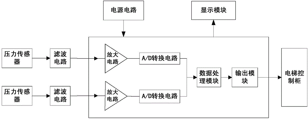
[0018] As shown in the figure, a brake monitoring device for a drum tractor provided by the present invention includes a power circuit, a pressure sensor, a signal processor and a display module; arm stress change signal; the pressure sensor inputs the stress change signal adopted into the signal processor for data processing to obtain the traction machine torque monitoring signal; the monitoring signal element is input to the display module for display; the power circuit and Signal processor connection.

[0019] The pressure sensor is a strain gauge; the strain gauge is arranged on a strain gauge carrier installed on the brake arm.

[0020] A filtering circuit is also included, and the filtering circuit is arranged between the pressure sensor and the signal processor.

[0021] The power supply circuit, signal processor and display module are arranged on the circuit board; the circuit board is arranged in the elevator control cabinet.

[0022] The strain gauge carrier is mad...

Embodiment 2

[0025] The difference between this embodiment and embodiment 1 is only:

[0026] This embodiment provides a drum type traction machine brake monitoring device, the principle of which is to pass the strain gauge through a special adhesive; the adhesive provided in this embodiment uses a polymeric adhesive as the connection between the strain gauge and the carrier (matrix) substance. Mainly divided into two categories: 1: Epoxy resin binder. 2:502 Glue. The main components and proportions of the former are: epoxy resin 100: ethylenediamine 7: dibutyl ester 5. The main components of the latter are: ethyl cyanoacrylate plus a small amount of plasticizer. In addition, the composition and ratio of the glue used as the insulation cover of the strain gauge is: epoxy resin 100: low molecular weight polyamide 100. Tightly adhere to the carrier and fix the carrier on the substrate (brake arm) that generates mechanical strain. When the substrate is stressed and the stress changes, the...


PUM


Abstract

The invention discloses a drum-type tractor band-type brake monitoring device. The device comprises a power circuit, a pressure sensor, a signal processor and a display module, wherein the pressure sensor, the signal processor and the display module are connected with the power circuit, the pressure sensor is arranged on a brake arm to be used for acquiring a brake arm stress change signal, the acquired stress change signal is input into the signal processor by the pressure sensor for data processing to obtain a tractor braking torque monitoring signal, and the monitoring signal is input into the display module to be displayed. According to the device, a stress gauge is adopted to acquire brake arm stress change data, and then whether tractor braking torque meets using requirements is judged according to stress change. The device can be used for indirectly monitoring tractor braking torque and is convenient to install, reliable in use and easy to maintain. The safety performance of a tractor is improved, the dimension of the tractor is not affected at all, and the strength performance of the whole tractor is guaranteed.

Description

technical field [0001] The invention relates to the field of elevator monitoring, in particular to an elevator traction machine brake monitoring device. Background technique [0002] With the rapid development of the modern construction industry and the widespread use of elevators, higher requirements are placed on the safety performance of elevator products. As the power equipment of the elevator, the safety performance of the traction machine is particularly important. [0003] At present, the braking device of the drum traction machine is mainly composed of an electromagnetic brake, two brake arms, and two brake springs. When the power is off, the brake arm is compressed by the brake spring to achieve the effect of holding the brake. When the power is turned on, the brake arm is pushed apart by the electromagnetic device to achieve the effect of releasing the brake. The monitoring of the brake state is mainly completed by two mechanical micro switches, and the brake sta...

Claims


Application Information

Patent Timeline
Patent Type & Authority Applications(China)
IPC IPC(8): B66B5/00F16D66/00
CPCB66B5/0006
Inventor 严曙辉赖豪杰励海云王新龙
Owner 宁波申菱机电科技股份有限公司
Why Eureka
Try Eureka