Railway structure of 10000-ton movable portal crane

A technology for moving doors and cranes, applied in rail systems, load hanging components, transportation and packaging, etc., can solve the problems of increasing the impact force and resistance of lifting equipment, the separation of the bottom plate, and the deformation of the rail in the horizontal direction, and achieve the movement resistance. small effect

Active Publication Date: 2015-05-13
HONGHUA OFFSHORE OIL & GAS EQUIP JIANGSU
View PDF7 Cites 8 Cited by
  • Summary
  • Abstract
  • Description
  • Claims
  • Application Information

AI Technical Summary

Problems solved by technology

Although this track structure can guide the walking of the lifting equipment, it has the following disadvantages: due to the increase in the use time of the lifting equipment, the concrete abutment j05 will settle, and once two adjacent concrete abutments j05 When uneven settlement occurs between adjacent concrete piers (that is, there is a height difference between adjacent concrete piers), the tra

Method used


Image

  • Railway structure of 10000-ton movable portal crane
  • Railway structure of 10000-ton movable portal crane
  • Railway structure of 10000-ton movable portal crane

Examples


Embodiment Construction

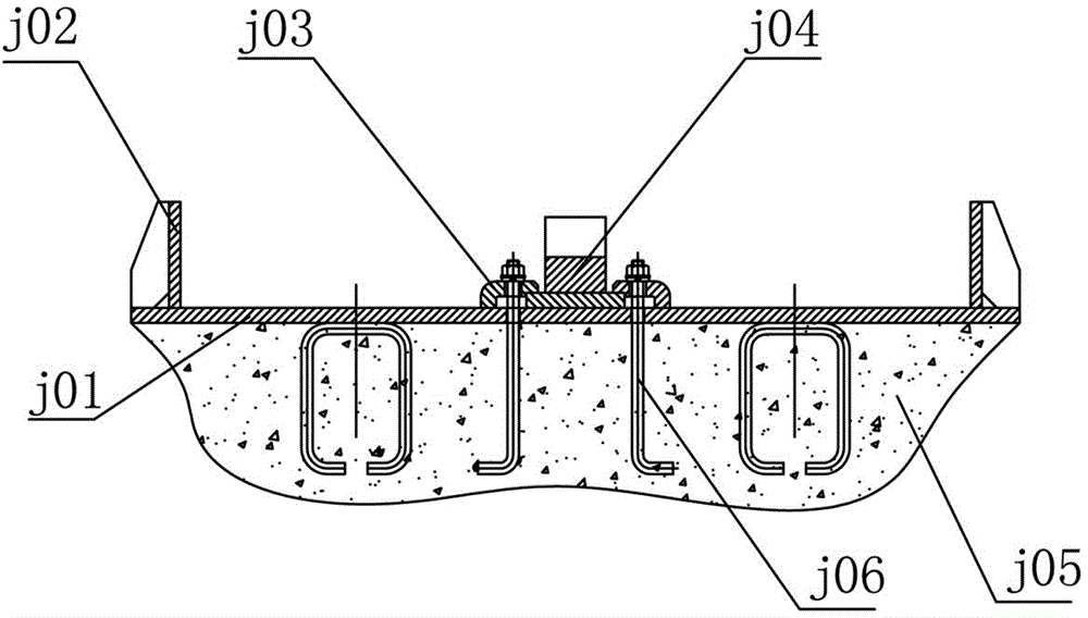
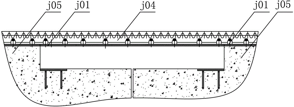
[0020] Such as Figure 4 to Figure 7 As shown, the track structure of a 10,000-ton movable gantry crane includes reinforced concrete j6 laid under track j10, pre-embedded plate j1 embedded in reinforced concrete j6, rack j4, pressure plate j3, two side The baffle j2; the upper surface of the embedded slab j1 exposes the reinforced concrete j6 and is kept flat with the surface of the reinforced concrete j6; the intermittent protrusions of the reinforced concrete j6 form a concrete abutment j5 intermittently distributed under the track j10 The cavity formed between the adjacent concrete piers j5 is provided with a track transition bridge j7; the track transition bridge j7 includes a top plate j71, a bottom plate j72 and a supporting plate j73 between the top plate j71 and the bottom plate j72; The top plate j71 of the track transition bridge j7 is flush with the embedded plate j1 located on the concrete abutment j5, and the bottom plate j72 is fixed on the embedded plate j1 loca...


PUM


Abstract

The invention discloses a railway structure of a 10000-ton movable portal crane. The railway structure comprises reinforced concrete, a pre-burying plate, a rack, a pressing plate and two side blocking plates, wherein the reinforced concrete is paved below a railway; the pre-burying plate is pre-buried in the reinforced concrete; the upper surface of the pre-burying plate exposes the reinforced concrete and keeps flatness with the surface of the reinforced concrete; discontinuous heaves of the reinforced concrete form concrete abutments disjunctively distributed below the railway; and a railway transition bridge is arranged in a cavity formed between the adjacent concrete abutments. By utilizing the railway structure of the 10000-ton movable portal crane, shock vibration of a hoisting device does not exist in the movement process, and the movement resistance is small. Meanwhile, potential safety accident risk caused by subsidence of concrete abutments arranged below the railway can be effectively avoided by the railway structure.

Description

technical field [0001] The invention belongs to the technical field of oil drilling and development, and in particular relates to a track structure of a 10,000-ton movable gantry crane. Background technique [0002] The conventional construction method of the offshore drilling platform is to build in the dock, which is limited by the lifting capacity of the gantry crane used in the shipyard and the dock. The shipyard usually decomposes the offshore platform or large components into small modules for construction in the workshop first. The modules are transported to the dock for assembly, that is, they are stacked part by part in the way of building blocks. The disadvantages of this construction method are: 1) The dock is the most important production resource for the shipyard, and it occupies the dock for a long time, which affects the acceptance of the shipbuilding contract by the shipyard; 2) The platform construction period is long and the construction efficiency is low. ...

Claims


Application Information

Patent Timeline
IPC IPC(8): B66C7/08
CPCB66C7/08
Inventor 张弭吴元良隋绍元熊壮李平黄雍李志刚李志诚陈崇杜斌武
Owner HONGHUA OFFSHORE OIL & GAS EQUIP JIANGSU
Why Eureka
Try Eureka