
Outer ring-blowing cooling and center oiling device for composite spinning

A technology of composite spinning and cooling device, applied in textile and papermaking, filament/thread forming, fiber processing, etc., can solve the problems of uneven and sufficient oiling, unguaranteed spinning quality, etc., to improve energy Efficiency, reduced energy consumption, low wind speed effects

Inactive Publication Date: 2015-05-13
海兴材料科技有限公司
View PDF7 Cites 7 Cited by
  • Summary
  • Abstract
  • Description
  • Claims
  • Application Information

AI Technical Summary

Problems solved by technology

The wheel is a circular plane body, the oil is evenly distributed on the wheel surface, and the yarn is oiled on the wheel surface in the form of a bundle, and the part of the filament in the tow that directly contacts the wheel surface is fully oiled, and the silk that does not directly contact the wheel surface The oiling of the strips cannot be guaranteed, the direct consequence is that the oiling cannot be uniform and sufficient, and the extension consequence is that the quality of spinning cannot be guaranteed

Method used


Image

  • Outer ring-blowing cooling and center oiling device for composite spinning

Examples


Embodiment 1

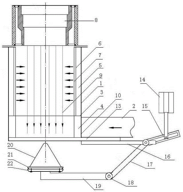
[0016] Embodiment 1: start the refrigerator, the cold air output by the refrigerator enters the air distribution channel 4 through the cold air input pipe 2 and the cold air inlet 10, and the cold air flow is circulated in the air distribution channel 4 due to the aperture limit of the air distribution hole. During the process, the cold air is evenly distributed to the surrounding air duct 5 through the air distribution holes of the cold air deflector 3 .

Embodiment 2

[0017] Embodiment 2: the cold wind that enters the ring blowing channel 5 moves up due to the limitation of the ring blowing hole aperture, and the cold wind is delivered to the ring between the ring blowing plate 6 and the ring blowing net 7 through the ring blowing holes on the ring blowing plate 6 space, and then enter the cooling channel where the spinning 9 falls in the ring blowing net 7 through the mesh of the ring blowing net 7, and the spinning 9 is cooled by blowing cold air from the outer ring.

Embodiment 3

[0018] Embodiment 3: At the same time when the spinning device starts to unload, the control system starts the pneumatic push-pull device 14 of the mobile unit, the high-pressure gas pushes the push-pull rod down, and the sliding pin at the connecting end of the push-pull rod moves in the chute of the slide rod 15 , push down the slide bar 15, because the connecting end of the slide bar 15 is connected at a fixed angle with one end of the connecting rod 17, and is positioned on the fixed bar 16 through the movable pin, the connecting rod 17 swings to the left with the movable pin as the center of the circle, and the connecting rod 17 The other end is connected with the support rod 19 by a hinge 18, and the connecting rod 17 pushes the support rod 19 to move toward the center of the outer ring cooling device. Because be connected by hinge 18 between connecting rod 17 and support bar 19, the movement of support bar 19 keeps horizontal state all the time, the oiling unit that is i...


PUM

PropertyMeasurementUnit
porosityaaaaaaaaaa

Abstract

An outer ring-blowing cooling and center oiling device for composite spinning comprises an outer shell, a cold air input pipeline, a cold air flow guide plate, an air distribution air flue, a ring-blowing air flue, a ring-blowing plate, a ring-blowing net, an oiling unit, a moving unit and a circulating oiling unit. A cold air inlet is formed in the lower end of the outer shell, the cold air input pipeline is connected with the cold air inlet, the cold air flow guide plate is horizontally installed above the cold air inlet, the air distribution air flue is arranged below the cold air flow guide plate, the ring-blowing plate is installed in the outer shell, the ring-blowing air flue is formed due to the distance between the ring-blowing plate and the outer shell, a plurality of air distribution holes are formed in the cold air flow guide plate, the ring-blowing net is installed in the ring-blowing plate, and a spun silk falling and cooling channel is arranged in the ring-blowing net; the oiling unit comprises a conical cover, an oiling plate and an oil receiving plate, an oiling lip is arranged on the periphery of the oiling plate, a distance fine tuning mechanism is arranged between the oiling plate and the conical cover, the circulating oiling unit determines oil supply amount by controlling the rotation speed of a variable-frequency oil pump, and the moving unit is pushed and pulled through a pneumatic pushing and pulling device so that the oiling unit can be moved to enter or exit.

Description

technical field [0001] The invention relates to an outer ring blowing cooling and center oiling device for composite spinning, which is a device for cooling and shaping the composite spinning filaments and for spinning oiling at the center of the spinning outlet, and belongs to the technical field of synthetic fiber composite spinning and chemical fiber machinery . Background technique [0002] The cooling process of composite spinning is the forming and setting process of spinning. After the chemical polymer is melted, it is formed into a filament by a spinning device, and the filamentous chemical is cooled and shaped by blowing cold air, and the filamentous chemical that is shaped after blowing cold air becomes a chemical fiber filament. The traditional method of blowing cold air is to use side blowing. The most prominent disadvantage of this method is that the energy consumption is particularly large, and the cooling wind is not uniform enough, which increases the produ...

Claims


Application Information

Patent Timeline
Patent Type & Authority Applications(China)
IPC IPC(8): D01D5/092D01D5/096
CPCD01D5/092D01D5/096
Inventor 欧阳文咸张连京冯永生
Owner 海兴材料科技有限公司
Learn More