Cement-soil mixing wall former

A cement-soil mixing and wall-forming machine technology, which is applied to sheet pile walls, earthwork drilling, water conservancy projects, etc., and can solve problems such as small thickness and unsatisfactory anti-seepage effect

Active Publication Date: 2015-05-13
江苏福克斯电气集团有限公司
View PDF9 Cites 18 Cited by
  • Summary
  • Abstract
  • Description
  • Claims
  • Application Information

AI Technical Summary

Problems solved by technology

[0002] At present, the cement-soil mixing wall machine used in anti-seepage reinforcement projects is to use multiple mixing drill bits and cement slurry to mix into multiple side-by-side round piles. The thickness of the overlapping part of each two adjacent round piles is relatively small. The anti-seepage effect is not ideal

Method used


Image

  • Cement-soil mixing wall former
  • Cement-soil mixing wall former

Examples


Embodiment Construction

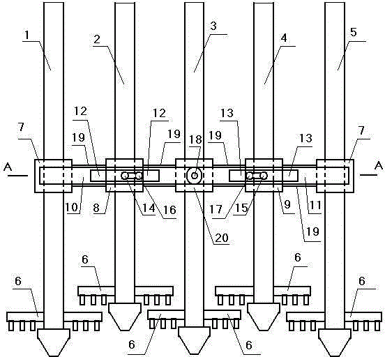
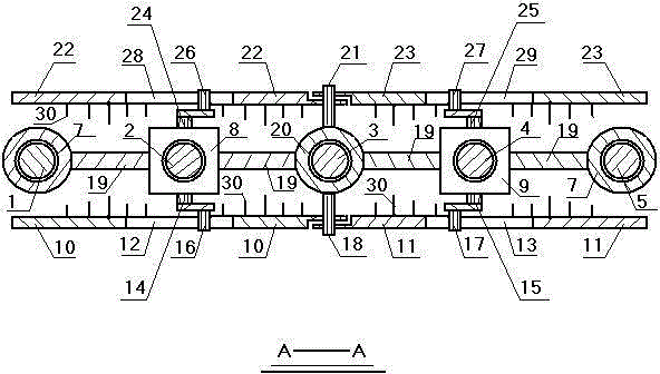
[0012] Accompanying drawing is a kind of concrete embodiment of the present invention, and this embodiment drilling rod ① 1, drilling rod ② 2, drilling rod ③ 3, drilling rod ④ 4, drilling rod ⑤ 5 lower ends are respectively provided with a drill bit 6, and drilling rod ① bottom is provided with a steel pipe Set ①7, the lower part of the drill pipe ② is provided with a drive box ①8, the lower part of the drill pipe ③ is provided with a steel pipe sleeve ②20, the lower part of the drill pipe ④ is provided with a drive box ②9, the lower part of the drill pipe ⑤ is provided with a steel pipe sleeve ①, the drill pipe ① The steel pipe sleeve ① and the drive box ① on the top, the drive box ① and the steel pipe sleeve ②, the steel pipe sleeve ② and the drive box ②, the steel pipe sleeve ① on the drive box ② and the drill pipe ⑤ are all fixed together with steel plates 19, and the front side of the drive box ① There is a crankshaft ①14, the crankpin ①16 of the crankshaft ① is inserted i...


PUM


Abstract

Disclosed is a cement-soil mixing wall former. A first crankshaft is arranged on the front side of a first driving box, a first crankshaft pin of the first crankshaft is inserted into a first rectangular hole of a first hinging arm, and a first straight pin is hinged to the right end of the first hinging arm and fixed to the front side of a second steel pipe sleeve; a third crankshaft is arranged on the back side of the first driving box, a third crankshaft pin of the third crankshaft is inserted into a third rectangular hole of a third hinging arm, and a second straight pin is hinged to the right end of the third hinging arm and fixed to the back side of the second steel pipe sleeve; a second crankshaft is arranged on the front side of a second driving box, a second crankshaft pin of the second crankshaft is inserted into a second rectangular hole of a second hinging arm, and a first straight pin is hinged to the left end of the second hinging arm; a fourth crankshaft is arranged on the back side of the second driving box, a fourth crankshaft pin of the fourth crankshaft is inserted into a fourth rectangular hole of a fourth hinging arm, and a second straight pin is hinged to the left end of the fourth hinging arm; multiple stirring blades are arranged on the first hinging arm, multiple stirring blades are arranged on the second hinging arm, multiple stirring blades are arranged on the third hinging arm, and multiple stirring blades are arranged on the fourth hinging arm.

Description

technical field [0001] The invention relates to a wall-forming machine, in particular to a cement-soil mixing wall-forming machine used in anti-seepage reinforcement projects. Background technique [0002] At present, the cement-soil mixing wall machine used in anti-seepage reinforcement projects is to use multiple mixing drill bits and cement slurry to mix into multiple side-by-side round piles. The thickness of the overlapping part of each two adjacent round piles is relatively small. The anti-seepage effect is not ideal. Contents of the invention [0003] The invention makes up for the above disadvantages and provides a cement soil mixing machine for forming walls. [0004] The present invention is achieved through the following technical solutions: [0005] A cement-soil mixing machine for forming walls, drill pipes ①, drill pipe ②, drill pipe ③, drill pipe ④, and drill pipe ⑤ are provided with a drill bit at the lower ends, a steel pipe sleeve ① is provided at the l...

Claims


Application Information

Patent Timeline
Patent Type & Authority Applications(China)
IPC IPC(8): E02D29/02
CPCE02D5/187E21B4/16
Inventor 张永忠
Owner 江苏福克斯电气集团有限公司
Why Eureka
Try Eureka