Door opener for automatic sector door opening

A door-opening device and sector-shaped technology, which is applied to the control mechanism of the wing leaf, wing leaf parts, door/window accessories, etc., can solve the problems of narrow application area, not meeting the needs of smart cities and smart homes, and short distances, so as to achieve easy promotion The effect of application, great practical value, and simple structure

Inactive Publication Date: 2015-05-13
JIANGXI HONGDU AVIATION IND GRP
9 Cites 1 Cited by

AI-Extracted Technical Summary

Problems solved by technology

The traditional door opener uses translation to open the door, which requires the door to be opened to both sides, and has special environmental requirements; there are very few fan-shaped doors in the market, which are only used in villa courtyard doors, and most of the control methods use infrared. Remote control, the di...

Abstract

A door opener for automatic sector door opening at least comprises a wheel, a coupler, a motor, a motor supporting plate, a fixed arm, an adjusting bolt, a clamping groove and a door. The wheel is connected with the motor through the coupler. The motor is fixed to the motor supporting plate. The fixed arm is fixedly connected with the end of the top side of the motor supporting plate. The adjusting bolt is inserted into the fixed arm. The door is connected with the fixed arm through a connecting piece. The clamping groove is formed in one side of the motor supporting plate. The door opener for automatic sector door opening is simple in structure, convenient to operate and low in cost, saves labor and time, adopts sector door opening, is suitable for daily domestic use, capable of being remotely controlled at the cloud end, capable of achieving networking with intelligent appliances, capable of enabling a door to become one part of the intelligent home, good in practicability and easy to apply and popularize and has great practical value.

Application Domain

Power-operated mechanism

Technology Topic

Industrial engineeringCoupling

Image

  • Door opener for automatic sector door opening
  • Door opener for automatic sector door opening
  • Door opener for automatic sector door opening

Examples

  • Experimental program(1)

Example Embodiment

[0011] The technical solutions in the embodiments of the present invention will be clearly and completely described below in conjunction with the accompanying drawings in the embodiments of the present invention. Obviously, the described embodiments are only a part of the embodiments of the present invention, rather than all the embodiments. Based on the embodiments of the present invention, all other embodiments obtained by those of ordinary skill in the art without creative work shall fall within the protection scope of the present invention.
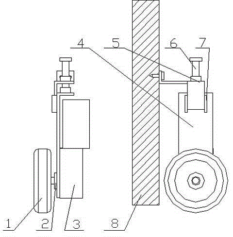
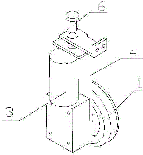
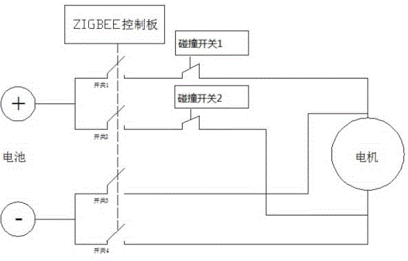
[0012] See Figure 1~3 In the embodiment of the present invention, a door opening device for automatic fan-shaped door opening includes at least wheel 1, coupling 2, motor 3, motor support plate 4, fixed arm 5, adjusting bolt 6, slot 7 and door 8. The wheel 1 is connected to the motor 3 through the coupling 2; the motor 3 is fixed on the motor support plate 4; the fixed arm 5 is fixedly connected to the top end of the motor support plate 4; the adjusting bolt 6 is inserted in In the fixed arm 5; the door 8 is connected with the fixed arm 5 through a connecting piece; the card slot 7 is opened on the side of the motor support plate 4.
[0013] Further, the door opening device also includes a battery and a ZIGBEE control board; the motor is connected to the wheels through a coupling, and the other end is connected to the ZIGBEE control board. When the ZIGBEE control board receives remote cloud or smart home central processor opening and closing control The signal, after signal processing, will send forward and reverse signals to the motor, and then pass it to the wheels to realize the intelligent fan-shaped opening and closing of the door, and feedback the status of the door open or closed to the cloud or smart home central processor.
[0014] The working principle of the present invention is: the ZIGBEE control board communicates with the cloud or the smart home central processing unit to obtain the door opening and closing command and feedback the door opening and closing signals. Such as figure 1 , The motor 3 is connected to the wheel 1 through the coupling 2, the motor 3 is fixed on the motor support plate 4, one end of the fixed arm is fixed to the door 8, and the other end is fixed to the motor support plate. The distance between the two is adjusted by the adjusting bolt 6. The function of the slot 7 is to ensure that the motor bracket can only move up and down, so as to control the distance and friction between the wheel and the bottom surface. The motor rotates forward and backward to drive the wheel forward and backward, and the door can be opened or closed.
[0015] When the ZIGBEE control board receives the door opening signal, after signal processing, the switch 1 and switch 4 of the control relay are closed to control battery power supply and current flow ( figure 2 (From top to bottom), and then control the forward rotation of motor 3. Motor 3 is connected to coupling 2, and the other end of coupling 2 is connected to wheel 1. The forward rotation of wheel 6 is used to open the door. When the door is opened in place, the collision switch on the door will hit the wall, disconnect the circuit, and feedback the signal of the door opening to the ZIGBEE control board, and the ZIGBEE control board will return the state of the door to the cloud or home central processor. In the same way, when the ZIGBEE control board receives the door closing signal, after signal processing, the switch 2 and switch 3 of the control relay are closed to control battery power supply and current flow ( figure 2 (From bottom to top), and then control the reversal of the motor 3 to drive the reversal of the wheels 6 to push the door in a fan-shaped manner. When the door is closed in place, the collision switch on the door will hit the door frame, disconnect the circuit, and feedback the door closed in place The signal is sent to the ZIGBEE control board, and the ZIGBEE control board returns the state of the door to the cloud or home central processing unit.
[0016] In the implementation of the present invention, the ZIGBEE control panel can be networked with smart home appliances, and the electronic lock can be used to make the door become a part of the smart home.
[0017] For those skilled in the art, it is obvious that the present invention is not limited to the details of the above exemplary embodiments, and the present invention can be implemented in other specific forms without departing from the spirit or basic characteristics of the present invention. Therefore, from any point of view, the embodiments should be regarded as exemplary and non-limiting. The scope of the present invention is defined by the appended claims rather than the above description, and therefore it is intended to fall within the claims. All changes within the meaning and scope of equivalent elements of are included in the present invention. Any reference signs in the claims should not be regarded as limiting the claims involved.
[0018] The above are only the preferred embodiments of the present invention and are not intended to limit the present invention. Any minor modifications, equivalent replacements and improvements made to the above embodiments based on the technical essence of the present invention shall be included in the technology of the present invention. Within the scope of protection of the program.

PUM

no PUM

Description & Claims & Application Information

We can also present the details of the Description, Claims and Application information to help users get a comprehensive understanding of the technical details of the patent, such as background art, summary of invention, brief description of drawings, description of embodiments, and other original content. On the other hand, users can also determine the specific scope of protection of the technology through the list of claims; as well as understand the changes in the life cycle of the technology with the presentation of the patent timeline. Login to view more.

Similar technology patents

Body condition measuring device

InactiveUS20050234351A1simple structure
Owner:DENSO CORP

Magnetic cooling apparatus and control method thereof

ActiveUS20130180263A1simple structure
Owner:SAMSUNG ELECTRONICS CO LTD

Dual-Drivetrain of Power-Assist Vehicle

InactiveUS20100181130A1enhance uphill momentumsimple structure
Owner:CHOU WEN CHENG

Classification and recommendation of technical efficacy words

  • Simple structure
  • easy to operate

Sharing system for air-conditioning coat

InactiveCN107440179ASimple structureeasy to wear
Owner:QINGDAO HAIER AIR CONDITIONER GENERAL CORP LTD

Feeding device of sorter of batteries plate

InactiveCN101357717ASimple structurecooperate well
Owner:NANJING NORMAL UNIVERSITY

Emergency parachuting device and method for multiple-rotor unmanned aerial vehicle

InactiveCN103895870Aavoid aircraft crashSimple structure
Owner:SOUTH CHINA AGRI UNIV +1

Lancet device

InactiveUS7303573B2inexpensively mass-producedeasy to operate
Owner:ABBOTT DIABETES CARE INC

Rapid and non-invasive optical detection of internal bleeding

InactiveUS20050065436A1easy to operaterapid and accurate result
Owner:HO WINSTON ZONH +2
Why Eureka
Try Eureka