Composite door and window sectional material with combination of internal and external metal sectional materials and middle integral heat-insulation sectional materials

A technology for metal profiles and door and window profiles, which is applied in windows/doors, building components, buildings, etc., and can solve the problem of low strength of joints without groups

Active Publication Date: 2015-05-13
王广武
View PDF7 Cites 2 Cited by
  • Summary
  • Abstract
  • Description
  • Claims
  • Application Information

AI Technical Summary

Problems solved by technology

2. Provide an integral heat-insulating profile with an internally and externally connected metal profile and an internal air cavity. By placing a connecting group corner in the air cavity of the middle heat-insulating profile adjacent to the internally and externally connecting metal profile, the connection of the heat-insulating profile of th

Method used


Image

  • Composite door and window sectional material with combination of internal and external metal sectional materials and middle integral heat-insulation sectional materials
  • Composite door and window sectional material with combination of internal and external metal sectional materials and middle integral heat-insulation sectional materials
  • Composite door and window sectional material with combination of internal and external metal sectional materials and middle integral heat-insulation sectional materials

Examples


Embodiment 1

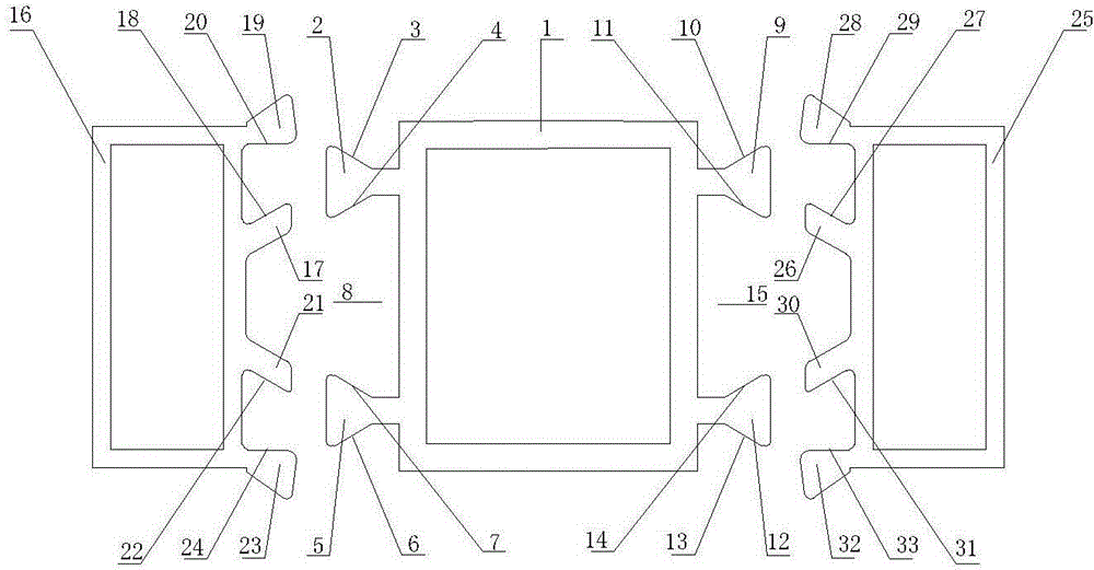
[0042] The schematic diagram of the partial assembly end face structure decomposition of the existing metal profiles and heat insulation profiles is as follows: figure 1 as shown, figure 2 yes figure 1 Schematic diagram of the longitudinal threading state of existing metal profiles and heat-insulating profiles, image 3 yes figure 1 Schematic diagram of the pressing state of the existing metal profiles and heat-insulating profiles, in which: 1 is the middle heat-insulating profile, 2 is the upper left fixing foot of the outer large and inner small dovetail, 3 is the pressing inclined surface of the upper left fixing foot, 4 is the inclined surface of the upper left fixing foot, 5 is the lower left fixed foot of the outer large inner small dovetail, 6 is the pressing slope of the lower left fixed foot, 7 is the upper slope of the lower left fixed foot, 8 is the outer small inner large dovetail groove on the left side of the heat insulation profile, 9 is the upper right of th...

Embodiment 2

[0048] Combining the inner and outer metal profiles with corner cavities and the integral heat-insulating profiles with corner cavities in the middle, the decomposed end surface structure diagram of window frame profiles is as follows Figure 4 as shown, Figure 4 The combined end face structure diagram is as follows Figure 5 As shown, among them: 50 is a heat insulation profile with a group corner cavity, 51 is an upper horizontal rib, 52 is an upper groove, 53 is a lower horizontal rib, 54 is a lower groove, 55 is an inner vertical rib, 56 is an inner small outer Large inner trapezoidal positioning groove, 57 is the inner upper connection protrusion, 58 is the inner upper connection groove, 59 is the lower support surface of the inner upper connection protrusion, 60 is the inner lower connection protrusion, 61 is the inner lower connection groove, 62 63 is an outer vertical rib, 64 is an outer trapezoidal positioning groove with a small inside and a large outside, 65 is an...

Embodiment 3

[0053] The structure diagram of the end surface of the window frame is composed of the metal profile with a set of corner cavities inside and outside and the overall heat-insulating profile in the middle cavity filled with thermal insulation materials. Figure 6 as shown, Figure 6 The combined end face structure diagram is as follows Figure 7 As shown, among them: 96 is a heat insulation profile with a group corner cavity, 97 is an inner vertical rib, 98 is an inner trapezoidal positioning groove with a small inside and a big outside, 99 is an inner upper connection protrusion, and 100 is an inner upper connection groove , 101 is the lower support surface of the inner upper connection protrusion, 102 is the inner lower connection protrusion, 103 is the inner lower connection groove, 104 is the upper support surface of the inner lower connection protrusion, 105 is the outer vertical rib, 106 is the inner small outer large 107 is the outer upper connection protrusion, 108 is ...


PUM


Abstract

The invention provides a composite door and window sectional material with a combination of internal and external metal sectional materials and middle integral heat-insulation sectional materials. An air cavity is formed in each middle integral heat-insulation sectional material; vertical ribs are arranged on two sides of each air cavity; transverse ribs are arranged on the top and the bottom of each air cavity; an internal trapezoidal positioning groove which has the small inside and the large outside is formed in the external middle portion of the vertical rib on the inner side of each air cavity; an external trapezoidal positioning groove which has the small inside and the large outside is formed in the external middle portion of the vertical rib on the outer side of each air cavity; a trapezoidal positioning projection which has the small outside and the large inside is arranged in the middle of each internal and external metal sectional material; an upper pressure plate and a lower pressure plate are respectively arranged on the top and the bottom of each internal and external metal sectional material; the trapezoidal positioning projections, which have the large insides and the small outsides, of the internal and external metal sectional materials are respectively inserted in the trapezoidal positioning grooves, which have the small insides and the large outsides, in the external middle portions of the vertical ribs of the middle integral heat-insulation sectional materials; the upper pressure of each internal and external metal sectional material which is subjected to plastic deformation is pressed on an upper V-shaped oblique plane of the corresponding upper projection or is pressed in the corresponding inner upper positioning groove; the lower pressure plate of each internal and external metal sectional material which is subjected to plastic deformation is pressed on a lower V-shaped oblique plane of a corresponding lower projection or is pressed in a corresponding inner lower positioning groove; and the inner sides of the internal and external metal sectional materials and the inner sides of the middle integral heat-insulation sectional materials are combined integrally.

Description

technical field [0001] The invention relates to door and window profiles for buildings. Background technique [0002] Patent CN201420344759 discloses a high-strength heat-insulating profile. The side of the heat-insulating profile opposite to the first aluminum profile and the second aluminum profile is respectively provided with at least one fixing foot, and the outer end surface of the fixing foot is provided with an inner concave or outer The convex positioning surface is provided with reinforcing plates on both sides of the heat-insulating profile, and the reinforcing plate and the heat-insulating profile are connected by at least one wire post, and the interior of the heat-insulating profile is a cavity structure. It has the characteristics of high strength and good heat resistance. [0003] This patent does not relate to filling the air cavity of the internal and external connecting profiles with foaming materials to improve the thermal insulation performance of the i...

Claims


Application Information

Patent Timeline
IPC IPC(8): E06B3/263
Inventor 王广武
Owner 王广武
Why Eureka
Try Eureka