A high back pressure plasma igniter

A plasma and high back pressure technology, applied in the direction of engine ignition, machine/engine, engine components, etc., can solve problems such as failure to work, and achieve the effect of strong ignition ability, light weight, and small size

Active Publication Date: 2017-02-01
XIAN AEROSPACE PROPULSION INST
View PDF6 Cites 1 Cited by
  • Summary
  • Abstract
  • Description
  • Claims
  • Application Information

AI Technical Summary

Problems solved by technology

[0003] The technical problem solved by the present invention is: to design a high back pressure plasma igniter, to overcome the disadvantages and deficiencies of existing plasma ignition technology that cannot work in high back pressure and variable back pressure environment, and to provide a high back pressure plasma igniter that can be used Plasma igniter up and running under high pressure

Method used


Image

  • A high back pressure plasma igniter
  • A high back pressure plasma igniter
  • A high back pressure plasma igniter

Examples


Embodiment Construction

[0017] The technical solutions of the present invention will be further described below in conjunction with specific implementation examples.

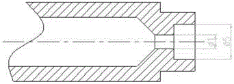
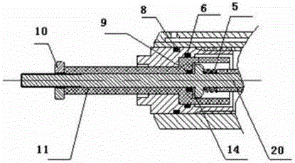
[0018] 1. see figure 1 and Figure 4 , a high back pressure plasma igniter is designed, including a housing 3, a cathode 20, an anode 1, an air inlet 7, a terminal post 13, a cyclone 2, a sealing ring structure and an insulating sleeve structure, an adjusting nut 12, Spring 5, support 17, restrictor 4 and inner nut 15, wherein the insulating sleeve adopts ceramic material, and the support also adopts ceramic material.

[0019] The inner cavity of the housing 3 is a concave structure, and the restrictor 4 is fixed at the bottom by a bracket 17 and an inner nut 15, and the external thread of the inner nut engages with the inner thread of the housing 3, so that the restrictor 4 And bracket 17 is clamped and fixed in the housing. The diameter of the air-connecting hole on the restrictor 4 is 0.5mm, and the air flow rate is stabilized by...


PUM


Abstract

The invention relates to a high-back-pressure plasma igniter. The problem that an existing igniter cannot work under the environment of high back pressure and variable back pressure is solved. According to the technical scheme, the high-back-pressure plasma igniter comprises a shell, a cathode, an anode, an air inlet, a binding post, a swirler, a sealing ring structure, an insulation sleeve structure, an adjusting nut, a spring, a restrictor and an inner nut. An air connecting hole in the restrictor is communicated with a through hole in the shell and the air inlet. External threads of the adjusting nut are meshed with internal threads on the shell. A boss arranged on the cathode is attached to a step structure of a second insulation sleeve, and the spring is compressed between the boss and a first insulation sleeve. The high-back-pressure plasma igniter has the advantages of being small in size, light, convenient to use, high in ignition capacity and capable of being started many times and running under high back pressure, and can be used as an ignition device of various heaters, combustion chambers, aero-engines and rocket engines.

Description

technical field [0001] The invention relates to an igniter, in particular to a high back pressure plasma igniter which can be used as various high chamber pressure burners. Background technique [0002] At present, the ignition devices of various heaters, combustion chambers, and thrust chambers of rocket engines and aeroengine test benches are mostly electric squibs, igniters, and spark plugs. Electric squibs and igniters have the disadvantages of poor safety and difficulty in multiple starts, while ordinary electric spark ignition has the disadvantages of low ignition energy and general ignition reliability. In order to realize the multiple ignition and repeated use of rocket engines and aeroengines, plasma ignition technology is an effective way. However, conventional plasma igniters are prone to power outages and flameouts under conditions of high back pressure and a sharp rise in back pressure. Contents of the invention [0003] The technical problem solved by the p...

Claims


Application Information

Patent Timeline
Patent Type & Authority Patents(China)
IPC IPC(8): F02P23/00
CPCF02P23/04
Inventor 王飞林榕方吉汉王妍张志豪魏建国韩先伟
Owner XIAN AEROSPACE PROPULSION INST
Why Eureka
Try Eureka