Sun-chasing device applied to solar street lamp

A technology for solar street lamps and solar panels, which is applied in the directions of solar thermal energy, solar thermal power generation, solar thermal collectors, etc., can solve the problems of long working hours, low photoelectric conversion efficiency of solar panels, uneconomical, etc., and achieve maintenance costs. Low, high photoelectric conversion efficiency, simple structure effect

Inactive Publication Date: 2015-05-13
JULU SHENTONG LAMPS
View PDF4 Cites 32 Cited by
  • Summary
  • Abstract
  • Description
  • Claims
  • Application Information

AI Technical Summary

Problems solved by technology

[0002] With the development of science and technology, energy conservation and environmental protection have become the goal pursued by various products today. Street lamps, as widely used lighting appliances, not only consume a huge amount, but also have high power, long working hours, and amazing power consumption. Erecting long-distance pipelines requires high investment costs and cumbersome maintenance, so solar street lights appear on the market
[0003] At present, in the structure of solar street lamps, there are mainly two types of solar panel power generation structures: (1) The solar panel is set to a fixed pitch angle and rotates with the direction of the sun, which is characterized by simple structure and low manufacturing cost. , but the photoelectric conversion efficiency per unit area of ​​the solar panel is low, and it cannot achieve the purpose of energy saving; (2) According to the direction of the sun's movement and the angle of incidence of sunlight, the way to adjust the posture of the solar panel in real time is characterized by the solar panel The photoelectric conversion efficiency per unit area is high, which can achieve the purpose of energy saving, but this kind of structure is complicated, and it needs to use two driving motors to drive two rotating shafts to realize its function. The manufacturing cost is too high for street lamps with huge usage , the reason is that the electricity usage fee saved by photoelectric conversion cannot fully offset its manufacturing cost, which is uneconomical

Method used


Image

  • Sun-chasing device applied to solar street lamp
  • Sun-chasing device applied to solar street lamp
  • Sun-chasing device applied to solar street lamp

Examples


Embodiment 1

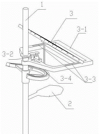
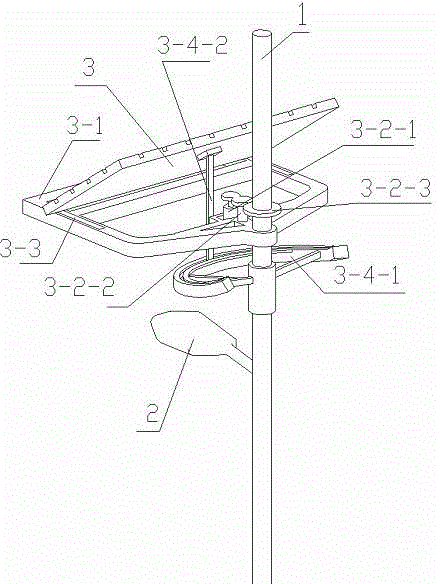
[0026] See attached Figure 1-5 It is the first embodiment of the present invention, a solar tracking device applied to solar street lamps, the structure includes a rotating bracket 3-1 hinged on the light pole 1, and a solar panel 3 arranged on the rotating bracket 3-1, which The key lies in: the rotating bracket 3-1 forms a horizontal rotation driving structure by means of the rotating driving mechanism 3-2, and the solar cell panel 3 forms a horizontal rotation driving structure by means of the horizontal displacement mechanism 3-3 and the angle adjustment limit mechanism 3-4. Bits form a linked vertical rotation adjustment structure. The lamp 2 is arranged below the sun tracking device.

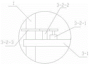
[0027] See attached image 3 The structure of the rotary drive mechanism 3-2 includes a stepper motor 3-2-1 arranged on the rotary support 3-1, a speed reducer 3-2-2 connected to the output shaft of the stepper motor 3-2-1, and a The output shaft of the speed reducer 3-2-2 is connected...


PUM


Abstract

The invention discloses a sun-chasing device applied to a solar street lamp, and belongs to the field of solar power generation devices. The sun-chasing device structurally comprises a rotating support and a solar cell panel, wherein the rotating support is hinged to a lamp pole, and the solar cell panel is arranged on the rotating support. The sun-chasing device is characterized in that with the help of a rotating driving mechanism, the rotating support forms a horizontal rotation driving structure, and with the help of combined limiting of a horizontal movement mechanism and an angle adjusting and limiting mechanism, the solar cell panel forms a linkage type perpendicular rotation adjusting structure. Through a combined limiting device composed of the horizontal rotation driving structure and the linkage type perpendicular rotation adjusting structure, the alignment angle and light-receiving angle of the solar cell panel can be adjusted in real time according to the sun motion, it is ensured that the solar cell panel works at the maximum photoelectric conversion efficiency, and the sun-chasing device is simple in structure and high in reliability.

Description

technical field [0001] The invention belongs to the field of solar power generation devices, and in particular relates to a solar tracking device applied to solar street lamps. Background technique [0002] With the development of science and technology, energy saving and environmental protection have become the goal pursued by various products today. Street lamps, as widely used lighting appliances, not only consume a huge amount, but also have high power, long working hours, and amazing power consumption. Erecting long-distance pipelines requires high investment costs and cumbersome maintenance, so solar street lights appear on the market. [0003] At present, in the structure of solar street lamps, there are mainly two types of solar panel power generation structures: (1) The solar panel is set at a fixed pitch angle and rotates with the direction of the sun, which is characterized by simple structure and low manufacturing cost. , but the photoelectric conversion efficie...

Claims


Application Information

Patent Timeline
Patent Type & Authority Applications(China)
IPC IPC(8): F21S9/03F21V21/108H02S20/32F21W131/103
CPCF21S9/035F21V21/14F21V21/30F21W2131/103H02S20/00F24S25/10F24S25/70F24S30/452Y02E10/47Y02E10/50
Inventor 孙现岭
Owner JULU SHENTONG LAMPS
Why Eureka
Try Eureka