Curved surface tool path contour error compensation method based tool location point correction

A contour error and compensation method technology, which is applied in the direction of instruments, computer control, simulators, etc., can solve the defects of the contour error reduction method, the reduced applicability of highly integrated CNC machine tools, and the inability to estimate the contour error of large-curvature machining trajectories, etc. question

Active Publication Date: 2015-05-13
DALIAN UNIV OF TECH
View PDF5 Cites 36 Cited by
  • Summary
  • Abstract
  • Description
  • Claims
  • Application Information

AI Technical Summary

Problems solved by technology

However, this method needs to improve the structure of the servo control system of each feed axis of CNC machine tools, which reduces the applicability of highly integrated CNC machine tools
[0005] In summary, none of the current contour error estimation methods can estimate the contour error of large-curvature machining trajectory curves, and the contour error reduction method also has defects.

Method used


Image

  • Curved surface tool path contour error compensation method based tool location point correction
  • Curved surface tool path contour error compensation method based tool location point correction
  • Curved surface tool path contour error compensation method based tool location point correction

Examples


Embodiment Construction

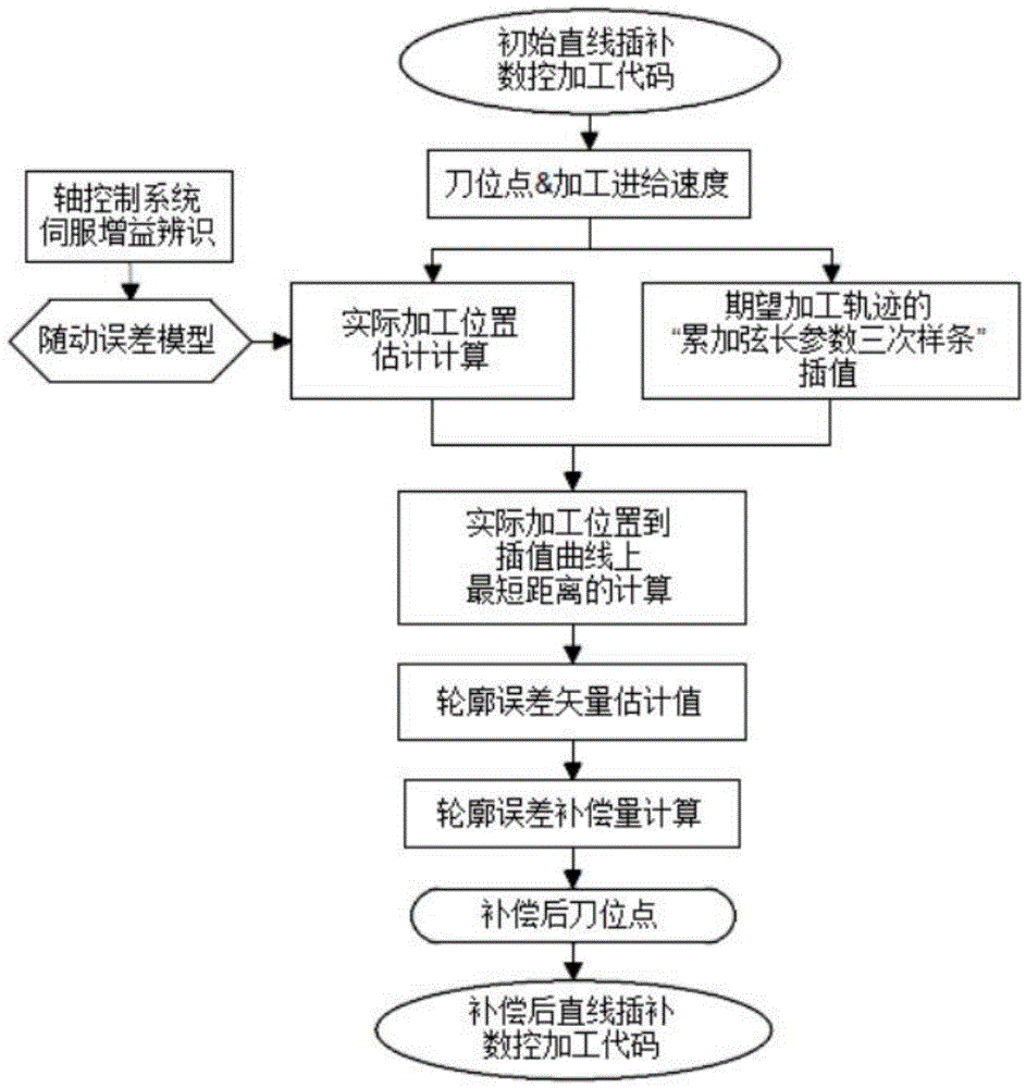
[0083] The specific implementation manner of the present invention will be described in detail in conjunction with the accompanying drawings and technical solutions.

[0084] In order to ensure the processing requirements of complex curved surface parts with high contour accuracy, the processing efficiency is low, which cannot meet the large demand for high contour precision complex curved surface parts in the rapid development of aerospace, energy and power and other fields. Machining with high feed rate is one of the important means to improve the machining efficiency of complex curved surface parts with high contour accuracy. However, in the "continuous path" operation mode of CNC machining, due to the limitation of the dynamic characteristics of the CNC machine tool, when the machining feed rate is high, the contour error of the machining trajectory curve of the CNC machine tool tool increases significantly, which in turn leads to a decrease in the contour accuracy of compl...


PUM


Abstract

The invention belongs to the field of numerical control machine tool dynamic error compensation and relates to a novel contour error estimation method, particularly to a curved surface tool path contour error compensation method based tool location point correction. The method comprises, on the basis of identifying the servo gain of a machining feed shaft control system, estimating practical machining points off line according to a following error model and linear interpolation machining codes; estimating contour error vectors according to a method similar to accumulated chord length parametric cubic spline of ideal tool paths; computing the contour error compensation according to the components of the contour error vectors on every axis to obtain compensated tool location points and further to generate linear interpolation numerical control machining codes for practical machining. The curved surface tool path contour error compensation method based tool location point correction can improve the dynamic precision of a numerical control machine tool and is high in precision, stable in computation, free from online measurement, easy to implement and wide in application range.

Description

technical field [0001] The invention belongs to the field of dynamic error compensation of numerical control machine tools, and relates to a new method for estimating contour errors and a new method for compensating contour errors of curved surface tool rails based on modification of tool position points. Background technique [0002] In high-end equipment in the fields of aerospace, energy and power, there are many complex curved surface parts that require high contour accuracy, such as aero-engine blades and marine integral impellers. Taking the blade of an aero-engine as an example, if the accuracy of its profile is not up to standard, it will directly affect its aerodynamic performance, which will lead to major safety hazards in the operation of the aero-engine. At present, in order to ensure the processing accuracy of such parts, the processing efficiency is low, and it cannot meet the rapid development of aerospace, energy and power fields for a large number of high-pr...

Claims


Application Information

Patent Timeline
Patent Type & Authority Applications(China)
IPC IPC(8): G05B19/404
CPCG05B19/404
Inventor 贾振元宋得宁马建伟王福吉高媛媛
Owner DALIAN UNIV OF TECH
Why Eureka
Try Eureka