
Gas turbine device

A technology of gas turbines and gas turbines, which is applied in the direction of gas turbine devices, jet propulsion devices, liquid fuel engines, etc., and can solve problems such as difficulty in effectively reducing low-frequency noise

Inactive Publication Date: 2015-05-13
KAWASAKI HEAVY IND LTD
View PDF7 Cites 1 Cited by
  • Summary
  • Abstract
  • Description
  • Claims
  • Application Information

AI Technical Summary

Problems solved by technology

On the contrary, it is difficult to effectively reduce the low-frequency noise generated from the gas turbine unit

Method used


Image

  • Gas turbine device
  • Gas turbine device
  • Gas turbine device

Examples


Embodiment Construction

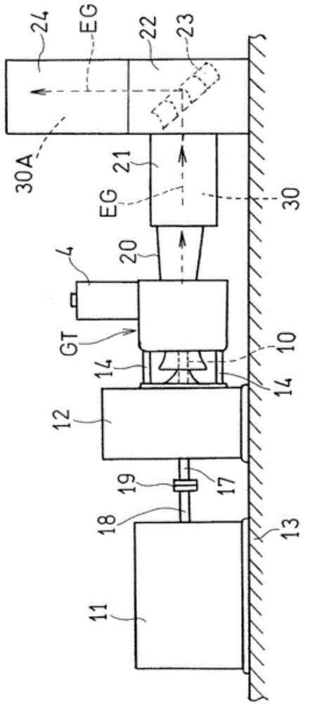
[0033] Hereinafter, preferred embodiments of the present invention will be described with reference to the accompanying drawings. exist figure 1 Among them, the heavy reducer 12 is fixed to the base 13 , and the gas turbine engine GT is cantilevered on the reducer 12 via a plurality of (four in this embodiment) struts 14 . The rotating shaft 10 of the gas turbine engine GT is connected to the connecting shaft on the input side of the speed reducer 12 , and the connecting shaft 17 on the output side of the speed reducer 12 is connected to the drive shaft 18 of the generator 11 which is the load of the gas turbine engine GT through the coupling 19 . connect. The exhaust gas EG discharged from the gas turbine engine GT in a substantially horizontal direction enters the exhaust chamber 22 through the exhaust diffuser 20 and the exhaust pipe 21, is deflected in a substantially vertical direction at the exhaust chamber 22, enters the muffler 24 above, and is The muffler 24 muffle...


PUM


Abstract

Provided is a gas turbine device that can effectively suppress low frequency noise and low frequency vibrations during low-load operation, without causing an increase in exhaust gas pressure loss. The gas turbine device is provided with the following: a gas turbine engine (GT) having an exhaust diffuser (20) that forms the upstream section of an exhaust gas flow path (30); exhaust struts (31) provided in the diffuser (20); and revolution suppression plates (32) that extend in the axial direction and are disposed on the downstream side of the exhaust struts (31) in the exhaust gas flow path (30).

Description

[0001] Related applications [0002] This application claims the priority of patent application 2012-188346 filed on August 29, 2012, the entire contents of which are incorporated by reference as a part of this application. technical field [0003] The present invention relates to a gas turbine device for driving a power machine such as a generator by a gas turbine engine. Background technique [0004] A large amount of high-frequency noise occurs in a gas turbine device, but the high-frequency noise can be effectively reduced by encapsulating the outer compartment or installing an intake and exhaust muffler. On the contrary, it is difficult to effectively reduce the low frequency noise generated from the gas turbine plant. Refer below Figure 5 and Image 6 This point will be explained. [0005] In a gas turbine device, the flow velocity of the exhaust gas from the last stage bucket of the gas turbine engine is generally relatively fast at about 300 to 400 m / sec. Therefo...

Claims


Application Information

Patent Timeline
Patent Type & Authority Applications(China)
IPC IPC(8): F02C7/24F01D25/00F01D25/30F02C7/00
CPCF01D25/30F05D2240/12F05D2260/96F05D2240/15F01D5/143F04D17/122F04D29/541
Inventor 山崎义弘细川恭史
Owner KAWASAKI HEAVY IND LTD
Learn More