Eureka AIR delivers breakthrough ideas for toughest innovation challenges, trusted by R&D personnel around the world.

Capacitance sensor interface circuit based on frequency switching

A capacitive sensor and interface circuit technology, applied in the direction of logic circuit interface device, logic circuit connection/interface layout, pulse shaping, etc., can solve application limitations, susceptibility to interference by temperature, noise and external factors, and poor accuracy and sensitivity High-level problems, to achieve the effect of reducing processing time, improving work efficiency and response speed, suppressing low-frequency noise and external factors

Active Publication Date: 2017-11-24
GUILIN UNIV OF ELECTRONIC TECH
View PDF9 Cites 1 Cited by
  • Summary
  • Abstract
  • Description
  • Claims
  • Application Information

AI Technical Summary

Problems solved by technology

The traditional capacitive sensor interface circuit directly amplifies the change in capacitance value and converts it into a change in voltage value, and most of them use the charge pump integration method, which needs to charge the charge pump for multiple cycles to generate a stable output voltage, resulting in The whole interface circuit has slow working speed, high power consumption, low accuracy and sensitivity, occupies too much chip area, and is easily disturbed by temperature, noise and external factors, which greatly restricts its application.

Method used


Image

  • Capacitance sensor interface circuit based on frequency switching
  • Capacitance sensor interface circuit based on frequency switching
  • Capacitance sensor interface circuit based on frequency switching

Examples


Embodiment Construction

[0016] In order to make the object, technical solution and advantages of the present invention clearer, the present invention will be further described in detail below in combination with specific examples and with reference to the accompanying drawings.

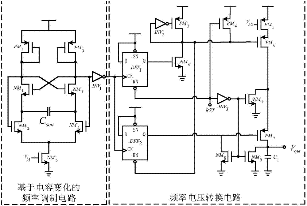
[0017] The present invention proposes a capacitive sensor interface circuit based on frequency conversion, such as figure 1 As shown, it is composed of frequency modulation circuit based on capacitance change and frequency voltage conversion circuit. The frequency modulation circuit based on capacitance variation converts different capacitance values ​​into square waves with different frequencies and a duty cycle of 50%. The frequency-to-voltage conversion circuit converts square waves of different frequencies into corresponding voltage signals after one input signal cycle, so that the generated voltage signal has a certain proportional relationship with the detected capacitance.

[0018] The above-mentioned frequency modul...


PUM


Abstract

The invention discloses a capacitance sensor interface circuit based on frequency switching. The circuit is composed of a frequency modulation circuit body based on capacitance change and a frequency voltage switching circuit body; the input end of the frequency modulation circuit body based on capacitance change forms the input end of the whole interface circuit and is connected with a measured capacitor; the output end of the frequency modulation circuit body based on capacitance change is connected with the input end of the frequency voltage switching circuit body; the output end of the frequency voltage switching circuit body forms the output end of the whole interface circuit; the frequency modulation circuit body based on capacitance change converts the measured capacitor value into a frequency value, and then frequency voltage switching circuit body converts the frequency value into a voltage value. The circuit can effectively inhibit the influence of noise on low-frequency positions, frequency signals can be converted into corresponding voltage signals only in a signal input period, the time-delay of outputting is reduced, and the reaction speed of the capacitance sensor interface circuit is greatly improved.

Description

technical field [0001] The invention relates to the technical field of integrated circuits, in particular to a capacitive sensor interface circuit based on frequency conversion. Background technique [0002] As a front-end component in the measurement system, the sensor can perceive the changes of external physical quantities, chemical quantities and biological information, and convert these non-electrical information into electrical signals that can be detected and processed by the electronic system according to certain rules. Sensors have been widely used in industrial production, transportation, national defense and military, and biomedical fields. With the continuous advancement of science and technology, sensors are gradually developing in the direction of miniaturization, integration, and intelligence. [0003] Compared with resistive sensors, capacitive sensors themselves do not consume any quiescent current, so they have been widely used in low-power portable mobile ...

Claims


Application Information

Patent Timeline
Patent Type & Authority Applications(China)
IPC IPC(8): H03K19/0175H03K5/01
CPCH03K5/01H03K19/017509Y02D10/00
Inventor 徐卫林刘俊昕孙晓菲李海鸥韦保林龚全熙
Owner GUILIN UNIV OF ELECTRONIC TECH
Why Eureka
Eureka Blog
Learn More