Electric rubber tapping knife

A tapping knife and electric technology, applied in forestry, application, agriculture, etc., can solve the problems of increased labor cost, high labor intensity, and no cutting if there is glue, so as to save labor cost, reduce labor intensity and save labor cost. Effect

Active Publication Date: 2015-05-20
曹建华 +3
View PDF6 Cites 14 Cited by
  • Summary
  • Abstract
  • Description
  • Claims
  • Application Information

AI Technical Summary

Problems solved by technology

[0002] At present, natural rubber tapping still uses the 100-year-old manual tapping method. Using a "V"-shaped traditional rubber tapping knife to cut rubber bark is not only labor-intensive and labor-intensive, but also requires relatively high technical requirements for rubber workers and is difficult to control. The depth and thickness of the rubber tapping port are good, it is easy to cause different depths of the glue line, damage the rubber tree wood layer, cause dead skin disease or other diseases, thereby reducing the latex output and causing greater losses to production
In the early days, some people also invented the use of mechanical force to drive the blade back and forth to cut rubber bark. Although it can reduce the labor intensity of rubber tapping, the efficiency is still very low, and it has not been widely used in production.
In addition, manual rubber tapping with traditional "V"-shaped knives has relatively high technical requirements for rubber workers. It takes one year or even several years to train a skilled rubber worker, and a lot of technical training costs will be invested
Under the current background of increasingly tense labor force, sharp increase in labor costs, and bad rubber price market conditions, production enterprises cannot make ends meet, resulting in an embarrassing situation where there is glue that cannot be cut, and there is no one to cut the rubber. The natural rubber industry is facing a severe test.

Method used


Image

  • Electric rubber tapping knife
  • Electric rubber tapping knife

Examples


Embodiment Construction

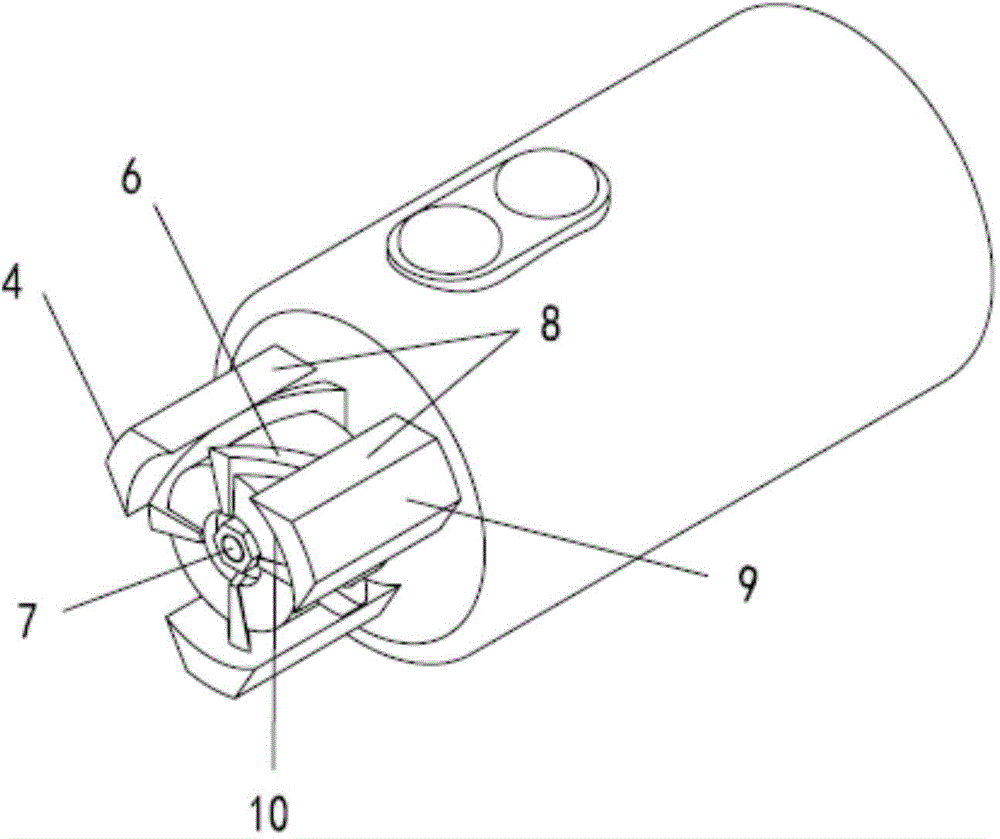
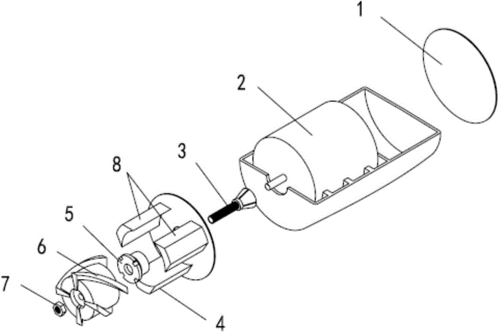
[0011] In order to describe the technical content and structural features of the present invention in detail, the following will be further described in conjunction with the embodiments and accompanying drawings.

[0012] Such as figure 1 , 2 As shown, the rubber electric tapping knife of the present invention includes a motor 2, a guide device and a rotary cutter head; the guide device is connected to the motor 2 shell through a fixing screw, the rotary cutter head is located in the guide device, and the rotary cutter head is connected to the motor through a rotating shaft; The guide device is made up of several arc trapezoidal guide pieces 4; each guide piece 4 is made up of an outer arc surface 9, an inner arc surface 10 and two waist surfaces 8; gaps are formed between adjacent guide pieces 4; Adjacent waist surfaces between adjacent guide pieces form a limit surface 8 on the same plane, and the limit surface 8 is parallel to the axis; the rotary cutter head is provided w...


PUM


Abstract

The invention discloses an electric rubber tapping knife. The electric rubber tapping knife comprises a motor, a guide device and a rotating knife head. The guide device is connected with an outer shell of the motor through a fixing screw, and the rotating knife head is arranged in the guide device. The guide device is composed of a plurality of arc-shaped trapezoidal guide sheets. Each guide sheet is composed of an outer arc face, an inner arc face and two waist faces. A notch is formed between every two adjacent guide sheets. Limiting faces on the same plane are formed by the adjacent waist faces between every two adjacent guide sheets and are parallel to the axis. A screw blade is arranged at the rotating knife head. The electric rubber tapping knife is used for replacing traditional manual rubber tree bark tapping and traditional V-shaped-knife rubber tree bark tapping, rubber tapping is easily, conveniently, rapidly and efficiently carried out, the labor intensity is reduced, the requirement for the rubber tapping technology is reduced, the labor cost is saved accordingly, and the benefits of the natural rubber industry is accordingly improved.

Description

technical field [0001] The invention relates to a rubber tapping knife used in the natural rubber industry driven by a motor, greatly improving the rubber tapping efficiency, reducing manual technology and labor intensity, and saving production costs. Background technique [0002] At present, natural rubber tapping still uses the 100-year-old manual tapping method. Using a "V"-shaped traditional rubber tapping knife to cut rubber bark is not only labor-intensive and labor-intensive, but also requires relatively high technical requirements for rubber workers and is difficult to control. The depth and thickness of the rubber tapping port are good, which can easily cause different depths of the glue line, damage the woody layer of the rubber tree, lead to the occurrence of dead skin disease or other diseases, thereby reducing the latex output and causing greater losses to production. In the early stage, someone invented to use mechanical force to drive the blade to stretch back...

Claims


Application Information

Patent Timeline
Patent Type & Authority Applications(China)
IPC IPC(8): A01G23/12
CPCA01G23/12
Inventor 曹建华张峰郑体刚陈帅
Owner 曹建华
Why Eureka
Try Eureka