
Low energy consumption lifting mixing bucket

A mixing tank and low energy consumption technology, which is applied in the direction of dissolving, mixing machines, chemical instruments and methods, etc., can solve the problems of high power consumption for stirring, easy sinking of materials, and high power configuration of motors, etc.

Active Publication Date: 2016-07-06
湖北省泽瀚实业有限公司
View PDF5 Cites 1 Cited by
  • Summary
  • Abstract
  • Description
  • Claims
  • Application Information

AI Technical Summary

Problems solved by technology

[0002] Stirring is a unit operation often used in metallurgy, chemical industry, food, medicine and other industrial fields. The most important thing about stirring is good material circulation, no dead space and low energy consumption. When the viscosity of the material is very high, stirring is not easy. Now Most of the mixing tanks are developed towards large capacity, high solid-liquid ratio, and strong stirring, but there are also defects such as high power consumption for stirring, easy jamming of material settlement, and difficulty in eliminating dead corners of stirring.
[0003] Existing large-size mixing tanks generally use long-axis multi-layer long paddles for low-speed mixing. The power of the motor is large and the radius of the stirring paddles is long. The material is easy to sink to the bottom. High, so the existing mixing tank can not meet the technical requirements of high viscosity, low energy consumption, large-scale mixing

Method used


Image

  • Low energy consumption lifting mixing bucket
  • Low energy consumption lifting mixing bucket
  • Low energy consumption lifting mixing bucket

Examples


Embodiment Construction

[0026] Now in conjunction with accompanying drawing, the present invention is described in further detail.

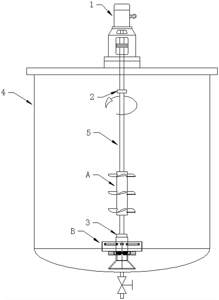
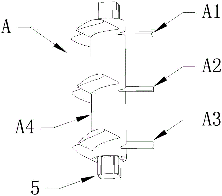
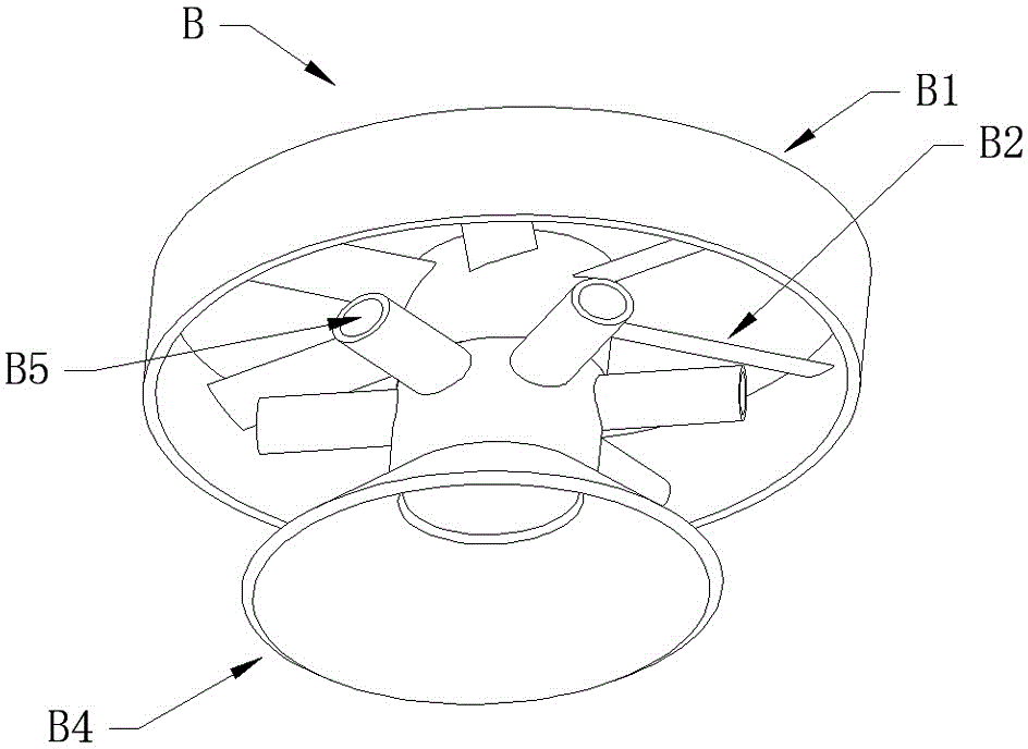
[0027] Such as figure 1 , figure 2 , image 3 , Figure 4 , Figure 5 and Figure 6 The low-energy-consumption lifting mixing tank shown includes a tank body 4, a motor and a reducer 1, and a stirring shaft. The stirring shaft is inserted into the tank body 4, and the motor and reducer 1 drive the stirring shaft to rotate. The stirring shaft is sequentially provided with suspension The lower jet agitator A and the bottom-sweeping agitator B, wherein the suspended lower jet agitator A is limited by the upper 2 and lower 3 positioning steps, and can float up and down; The shaft is the spline shaft 5, and the shaft sleeve is also the spline shaft sleeve A4. The spline shaft sleeve A4 can move on the spline shaft 5, and the paddles A1, A2, and A3 are welded on the spline shaft sleeve A4; The device B includes the stirring shaft and the outer cylinder B1, the stirring...


PUM


Abstract

The invention discloses a low-energy-consumption lifting mixing barrel. A mixing shaft is inserted into a barrel body, a motor and a reducer drive the mixing shaft to rotate, the mixing shaft is sequentially provided with a lower suspension spraying mixer and a bottom sweeping mixer from top to bottom, wherein the lower suspension spraying mixer is limited by an upper positioning step and a lower positioning step and can float up and down; the lower suspension spraying mixer comprises a mixing shaft, a shaft sleeve and a paddle, wherein the mixing shaft is a spline shaft, the shaft sleeve is also a spline shaft sleeve, the spline shaft sleeve can move on the spline shaft, and the paddle is welded on the spline shaft sleeve; the bottom sweeping mixer comprises a mixing shaft and an outer barrel, the mixing shaft and the outer barrel are welded into a whole by virtue of a paddle, the mixing shaft extends downward and forms a hollow cylinder, then the hollow cylinder extends to form a cone, and the outer wall of the cylinder is communicated with a jet pipe; and a blade tilt is gradually increased from top to bottom. The low-energy-consumption lifting mixing barrel has the characteristics that energy consumption is low, material circulation is good, deposition at the bottom is hardly caused, no mixing dead angle is formed, and light-load staring can be still realized even materials are sedimented due to long-time power failure, so that the low-energy-consumption lifting mixing barrel has a broad application prospect.

Description

technical field [0001] The invention relates to a stirring device, in particular to a low energy consumption lifting mixing barrel. Background technique [0002] Stirring is a unit operation often used in metallurgy, chemical industry, food, medicine and other industrial fields. The most important thing about stirring is good material circulation, no dead space and low energy consumption. When the viscosity of the material is very high, stirring is not easy. Now Most of the mixing tanks are developed towards large capacity, high solid-liquid ratio, and strong stirring, but there are also defects such as high power consumption for stirring, easy jamming of material sedimentation, and difficulty in eliminating dead corners of stirring. [0003] Existing large-size mixing tanks generally use long-axis multi-layer long paddles for low-speed mixing. The power of the motor is large and the radius of the stirring paddles is long. The material is easy to sink to the bottom. High, s...

Claims


Application Information

Patent Timeline
Patent Type & Authority Patents(China)
IPC IPC(8): B01F13/10
Inventor 银永忠姚茂君
Owner 湖北省泽瀚实业有限公司
Learn More