Rolling tool

A rolling and tooling technology, which is applied in the direction of manufacturing tools, metal processing equipment, metal material coating technology, etc., can solve problems such as offset and coating surface separation, and achieve the effect of avoiding offset and good adhesion

Active Publication Date: 2015-05-20
HOFFMANN GMBH QUALITATSWERKZEUGE
View PDF7 Cites 7 Cited by
  • Summary
  • Abstract
  • Description
  • Claims
  • Application Information

AI Technical Summary

Problems solved by technology

[0005] However, it has been found that forces acting on the coating, especially in the direction of extension of the groove, can also cause the coating to detach or deflect relative to the workpiece surface

Method used


Image

  • Rolling tool
  • Rolling tool
  • Rolling tool

Examples


Embodiment Construction

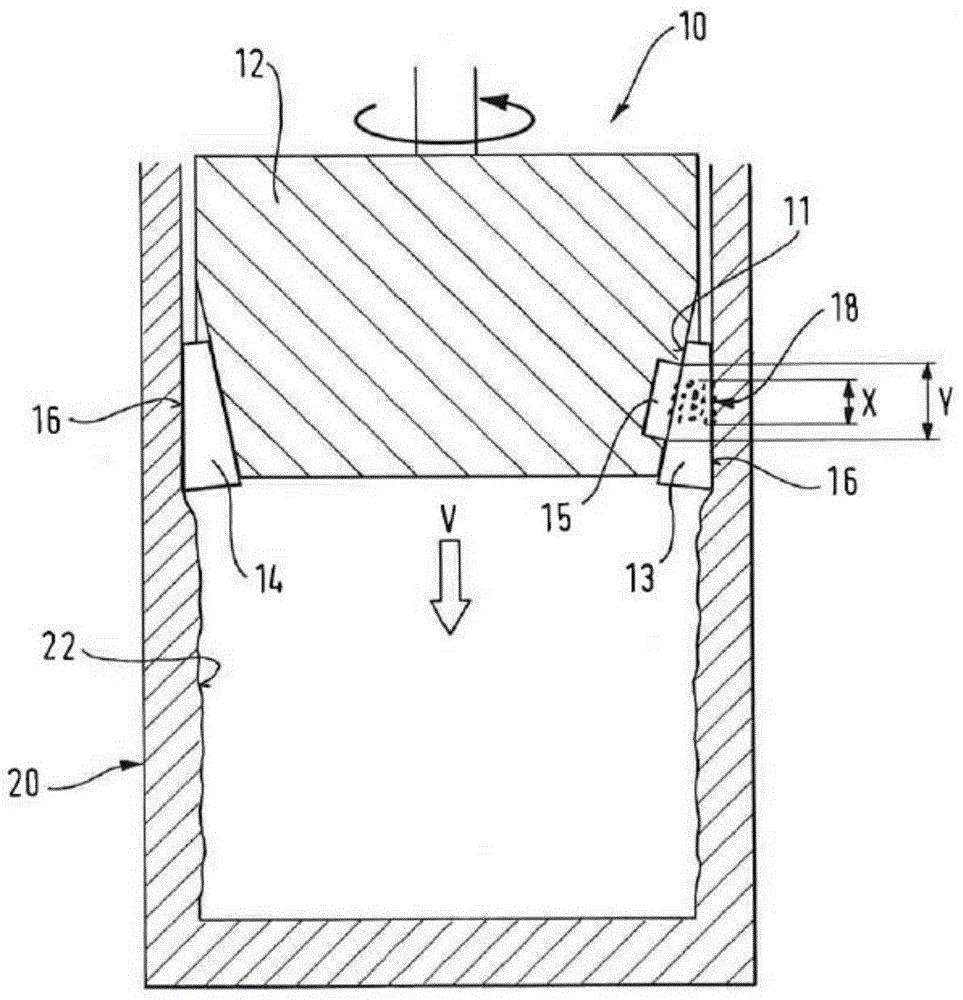
[0034] figure 1 A schematic side view of a first embodiment of a rolling tool 10 according to the invention is shown. The rolling tool is passing through the substantially cylindrical section of the tubular workpiece 20 in the feed direction and simultaneously rotates about its own axis. For this purpose, the rolling tool can be clamped by means of rollers or similar. Of course, the rolling tool can optionally also be fixedly clamped, while the workpiece is moved rotatably toward the rolling tool 10 .

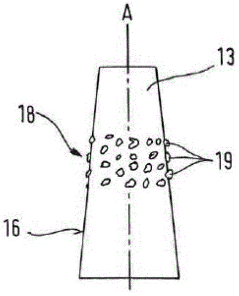
[0035] Before machining, the outer diameter of the rolling tool is slightly larger than the inner diameter of the workpiece 20, so that the machined inner surface 22 of the workpiece 20 is plastically deformed and strengthened radially outward during machining. Unlike conventional rolling tools, however, the inner wall of the workpiece 20 is not completely smoothed, but is roughened by the protrusions 19 of the rolling tool 10 .

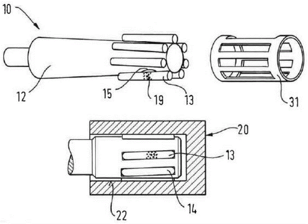
[0036] The rolling tool 10 has a rotatably m...


PUM


Abstract

The invention relates to a rolling tool with a roller support protruding in a feed direction. One or more rolling rollers are arranged on the periphery of the roller support and can rotate with the axis of the rollers. The rolling tool is used for processing a workpiece surface. One of the rolling rollers has a contact surface for contacting the workpiece. The contact surface has a rough segment with a projection protruding outwards in a radial direction about the axis of the rollers. The invention also relates to a method for processing a workpiece surface with the rolling tool in the invention.

Description

technical field [0001] The invention relates to a rolling tool with a roller carrier protruding in the feed direction, on which roller carrier one or more rolling rollers for machining the surface of a workpiece are arranged so as to be rotatable around the roller axis in the circumferential direction son. Background technique [0002] Rolling tools are used to smooth rough surfaces without cutting by rolling rolling elements in the form of rollers. Metal surfaces generally have a surface structure or roughness after rough machining such as turning, milling, grinding, etc., which can be completely smoothed by rolling processes for finishing. In this case, the roller carrier, which carries the rolling rollers, moves in a circumferential direction in a rotational manner and radially over the workpiece surface to be smoothed, wherein the rolling rollers contact the workpiece surface. Given the pressing force of the rolling roller, the surface layer of the workpiece becomes sm...

Claims


Application Information

Patent Timeline
Patent Type & Authority Applications(China)
IPC IPC(8): B23P9/02C23C4/02
CPCB23P9/02C23C4/02B21H7/18B24B39/023
Inventor 卡尔海因茨·哈恩
Owner HOFFMANN GMBH QUALITATSWERKZEUGE
Why Eureka
Try Eureka