Silent chain

a technology of silent chain and pin hole, which is applied in the direction of driving chains, heat treatment equipment, furniture, etc., can solve the problems of “wear elongation” of the chain, impairing engine performance, and so on, and achieves the effect of hardening the surface of the workpiece, removing roughness and shear drops, and improving the surface accuracy of the punched blank

Active Publication Date: 2009-06-16
TSUBAKIMOTO CHAIN CO
View PDF11 Cites 6 Cited by
  • Summary
  • Abstract
  • Description
  • Claims
  • Application Information

AI Technical Summary

Benefits of technology

[0010]The term “shaving,” as used herein, refers to the use of a bar-shaped or column-shaped tool, having a contour that slightly overlaps the contour of a workpiece blank, to remove a thin portion of a surface of the workpiece blank. The contour of the shaving tool can be similar to the contour of a punch used to form the blank, but the dimensions of the shaving tool differ from those of the punch by an amount corresponding to the amount of material to be removed in the shaving process. The shaving step removes roughness and shear drops generated during punching, and improve the surface accuracy of the punched blank.
[0011]A silent chain made in accordance with the invention can transmit power in the timing drive of an engine, for example, without producing large amounts of noise. When the silent chain is used as a timing chain in a direct injection engine, soot entering the pin holes of the link plates together with engine oil is retained within the dimples formed on the inner surfaces of the pin holes. As a result, the abrasive action of the soot is reduced, wear of the inner surfaces of the pin holes is suppressed, and chain wear elongation is reduced. In addition, the inner surfaces of the pin holes are hardened as a result of residual compression stress, and therefore the fatigue strength of the timing chain is improved.
[0012]If dimples are formed by shot-peening on the sprocket tooth-engaging surfaces of the link plates, retention of oil within those dimples similarly reduces the abrasive action of soot on the sprocket tooth-engaging surfaces, and significantly reduces sprocket tooth wear, and also improves the fatigue strength of the sprocket tooth-engaging surfaces.
[0013]Similarly, if dimples are formed on the back surfaces of the link plates by shot-peening, oil retained within the dimples on the back surfaces of the link plates significantly reduces wear of the sliding contact surfaces of chain guides and tensioner levers engaged with the chain, and also improves the fatigue strength of the back surfaces of the link plates.
[0014]When the inner surfaces of the pin-receiving holes are subjected to a shaving step prior to shot-peening, the dimensional accuracy of the inner surfaces of the holes is improved, and a more uniform load distribution is achieved along the direction of pin insertion. Consequently, chain wear elongation due to uneven contact between the connecting pins and the inner surfaces of the pin-receiving holes is reduced. Shaving of the sprocket tooth-engaging surfaces and the back surfaces of the link plates prior to shot peening also produces beneficial effects, in that the improvement of surface accuracy resulting from the shaving step reduces uneven wear.

Problems solved by technology

However, in a direct injection engine, combustion residues such as carbon and similarly abrasive substances, generally referred to as “soot,” are generated by incomplete combustion of fuel such as diesel fuel.
When the shave surfaces of the chain are exposed to this soot, especially when the soot, along with engine lubricating oil, enters the connecting pin holes in the link plates, the soot promotes wear between the inner surfaces of the pin holes and the outer surfaces of the pins.
The wear of the pin holes, and of the pins, results in “wear elongation” of the chain over time.
Wear elongation, in turn, impairs engine performance, and brings about the need for early timing chain replacement.
The soot in a direct injection engine can also adhere to sprocket tooth-engaging surfaces of the link plates and to the backs of the link plates, causing wear of the sprocket teeth, and link plate teeth as well as wear of chain guide shoes and tensioner lever shoes on which the backs of the link plates slide.
Excessive wear of these components significantly shortens their useful life.

Method used


Image

  • Silent chain
  • Silent chain
  • Silent chain

Examples


Embodiment Construction

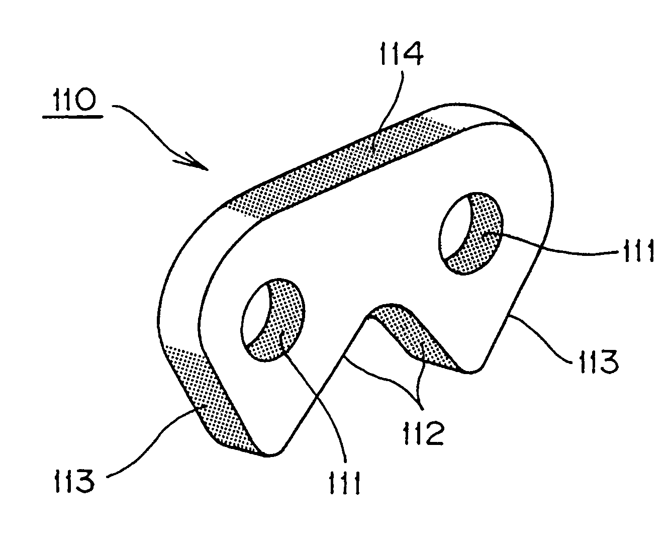
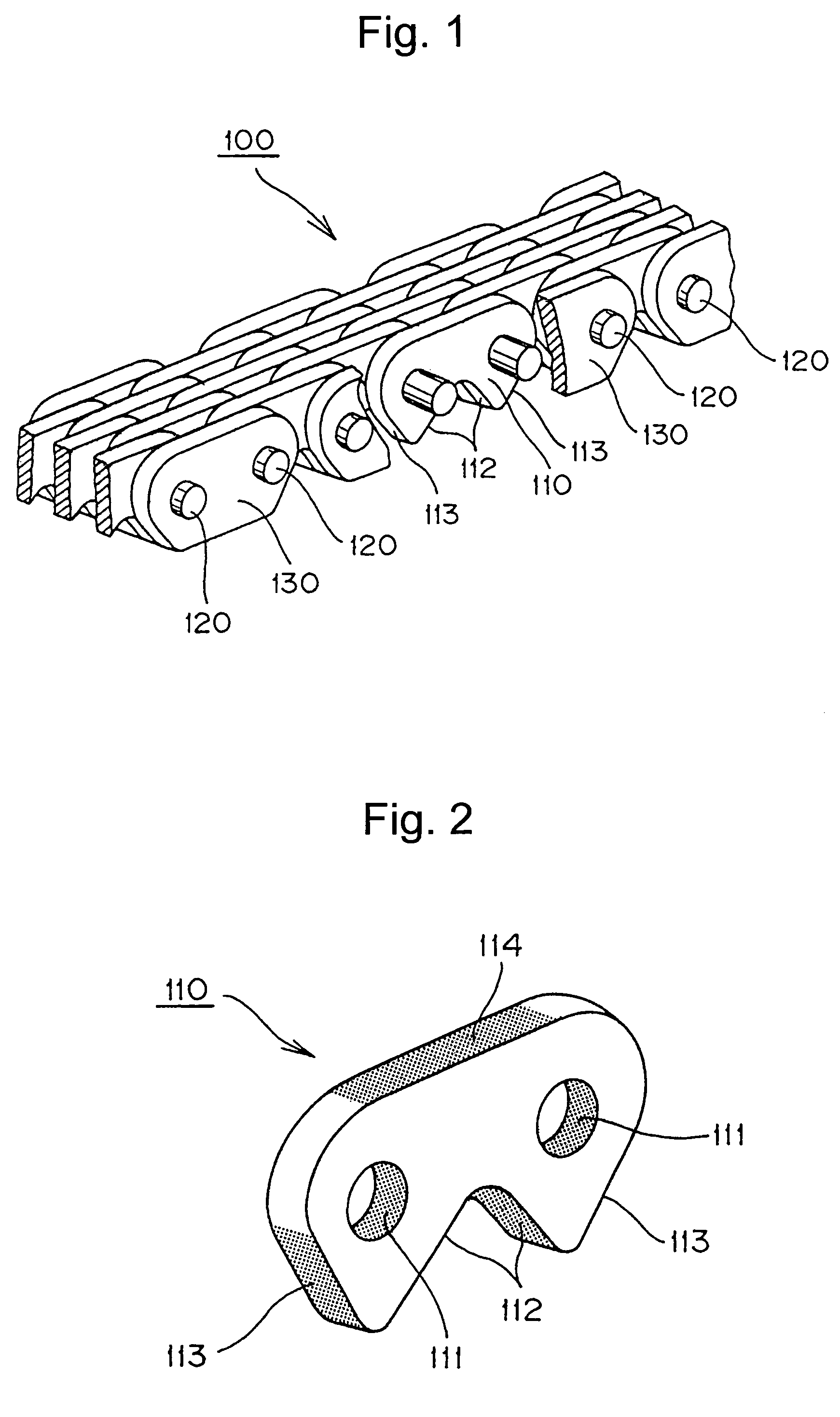
[0021]As shown in FIG. 1, the silent chain 100, in accordance with the invention, is formed by arranging link plates 110 in rows extending widthwise with respect to the longitudinal direction of the chain, interleaving the rows, and connecting the rows by inserting connecting pins 120 through pin-receiving holes in the link plates. The pins fit through the pin-receiving holes in the link plates with a suitable clearance to allow articulation of the chain. However, the pins are fixed to guide plates 130 provided along both sides of the chain at opposite ends of every second link plate row.

[0022]Each link plate has a pair of teeth, and each tooth has an inner surface 112 and an outer surface 113. Depending on the transmission design, inner surfaces 112, outer surfaces 113, or both, can serve as sprocket tooth-engaging surfaces. The link plates also have back surfaces 114 (FIG. 2), which slide on a chain guide, a tensioner lever, or both, in a typical engine timing transmission.

[0023]T...


PUM

PropertyMeasurementUnit
wear elongationaaaaaaaaaa
temperatureaaaaaaaaaa
wear elongationaaaaaaaaaa

Abstract

Link plates of a silent chain are produced by first shaving the inner surfaces of the connecting pin holes, the sprocket tooth-engaging surfaces, and the backs of the link plates, and then forming dimples on those surfaces by shot-peening.

Description

CROSS-REFERENCE TO RELATED APPLICATION[0001]This application claims priority on the basis of Japanese patent application 2005-228568, filed Aug. 5, 2005. The disclosure of Japanese application 2005-228568 is hereby incorporated by reference.FIELD OF THE INVENTION[0002]The invention relates to a silent chain of the type typically used as a timing chain in an internal combustion engine. The invention relates more particularly to a silent chain having wear-resistant properties making it especially useful as a timing chain in a direct injection engine, in which a fuel, for example diesel fuel, is directly injected the engine cylinders and ignited by the high temperature resulting from compression of air in the cylinders.BACKGROUND OF THE INVENTION[0003]Japanese Laid-Open Patent Publication No. 2003-260536 describes a silent chain composed of interleaved, toothed, link plates and connecting pins, in which sprocket tooth-engaging surfaces of inner flanks and outer flanks of the link plate...

Claims


Application Information

Patent Timeline
Patent Type & Authority Patents(United States)
IPC IPC(8): B21L9/04F16G13/04
CPCB21L9/02B21L9/04B21L99/00C21D9/0087F16G13/04C21D7/06Y10T29/479
Inventor SHIMAYA, KAZUHIKONAGAO, KENICHIOGO, TOSHITAKA
Owner TSUBAKIMOTO CHAIN CO
Why Eureka
Try Eureka