Pipe end flattening feeding structure

A technology of flat ends and joints at pipe ends, which is applied to metal processing machinery parts, driving devices, metal processing equipment, etc., can solve problems such as unsuitable steel pipes, and achieve high work efficiency, good effect, and wide application range

Active Publication Date: 2015-05-20
ZHEJIANG KINGLAND & PIPELINE TECH
View PDF5 Cites 4 Cited by
  • Summary
  • Abstract
  • Description
  • Claims
  • Application Information

AI Technical Summary

Problems solved by technology

Pipe end flattening is a turning process. The steel pipe is kept fixed, the tool is rotated and fed at a certain speed, so that the tool removes the burr on the pipe end, makes the pipe end perpendicular to the axis of the steel pipe, and ensures a flat surface. However, the existing pipe The end leveling device uses the clamp to clamp the steel pipe, drives the steel pipe to rotate, and then uses the tool to cut. This method is acceptable for steel pipes with relatively small diameters and short lengths. However, for steel pipes with relatively large diameters and long lengths Longer steel pipes are not suitable

Method used


Image

  • Pipe end flattening feeding structure
  • Pipe end flattening feeding structure
  • Pipe end flattening feeding structure

Examples


Embodiment Construction

[0019] The present invention will be described in further detail below in conjunction with the accompanying drawings.

[0020] This specific embodiment is only an explanation of the present invention, and it is not a limitation of the present invention. Those skilled in the art can make modifications to this embodiment without creative contribution as required after reading this specification, but as long as they are within the rights of the present invention All claims are protected by patent law.

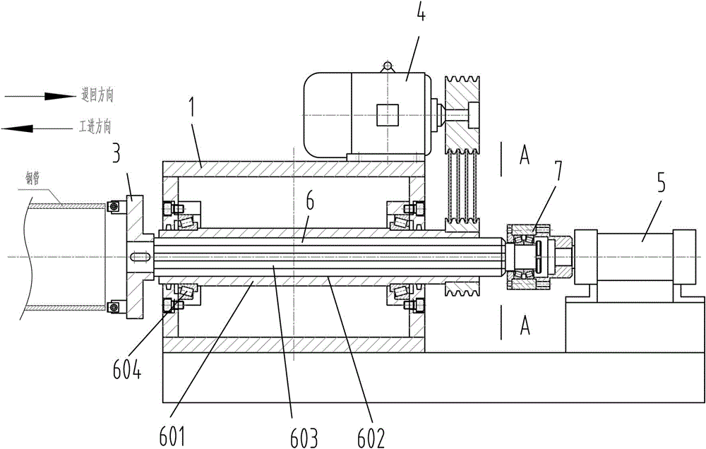
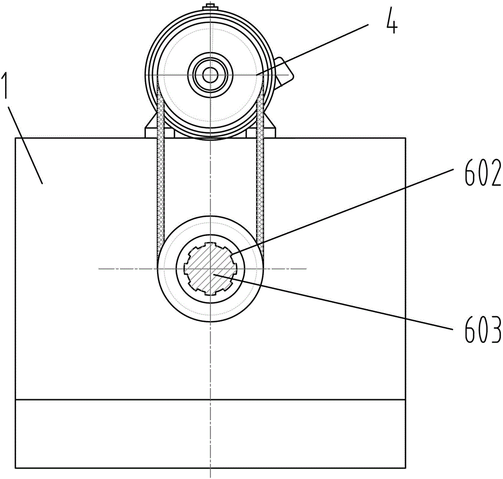
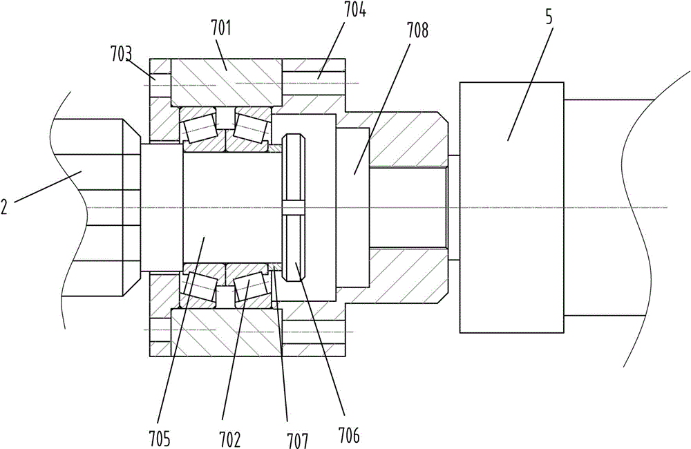
[0021] Example: such as figure 1 , 2 , a pipe end flat head feeding structure shown in 3, including a base 1, a rotating shaft 2 arranged on the base 1, a tool mounting plate 3 fixed on the end of the rotating shaft 2, a The rotary drive part 4 for driving the rotary shaft 2 to rotate, the linear drive part 5 for driving the rotary shaft 2 to move axially, and the rotary drive part 5 arranged between the base 1 and the rotary shaft 2 for The rotary drive part 4 drives the rotar...


PUM


Abstract

The invention discloses a pipe end flattening feeding structure which comprises a base, a rotary shaft arranged on the base, a cutter installation disc fixed to the end of the rotary shaft, a rotary drive part arranged on the base and used for driving the rotary shaft to rotate, a linear drive part used for driving the rotary shaft to move axially and a combination part arranged between the base and the rotary shaft and used for making the rotary drive part drive the rotary shaft to rotate and making the linear drive part drive the rotary shaft to move linearly. The pipe end flattening feeding structure is simple, convenient to manufacture and wide in application range; when the end face of a steel pipe is flattened, the steel pipe is fixed, a cutter is rotated, the flattening speed is high, the effect is good, the retracting speed of the rotary shaft is high, and the work efficiency of a whole device is high.

Description

technical field [0001] The invention relates to the technical field of steel pipe processing, in particular to a feeding structure for processing the end face of a steel pipe. Background technique [0002] In the production process of steel pipes, it is often necessary to carry out flat end treatment on both ends of the steel pipes to ensure the geometric dimensions of the pipe ends and the needs of later welding or butt joints. Pipe end flattening is a turning process. The steel pipe is kept fixed, the tool is rotated and fed at a certain speed, so that the tool removes the burr on the pipe end, makes the pipe end perpendicular to the axis of the steel pipe, and ensures a flat surface. However, the existing pipe The end leveling device uses the clamp to clamp the steel pipe, drives the steel pipe to rotate, and then uses the tool to cut. This method is acceptable for steel pipes with relatively small diameters and short lengths. However, for steel pipes with relatively larg...

Claims


Application Information

Patent Timeline
Patent Type & Authority Applications(China)
IPC IPC(8): B23Q5/32B23Q5/26B23Q5/10
CPCB23Q5/10B23Q5/26B23Q5/32
Inventor 郑荣史文华朱文闯魏忠平茹新龙
Owner ZHEJIANG KINGLAND & PIPELINE TECH
Why Eureka
Try Eureka