

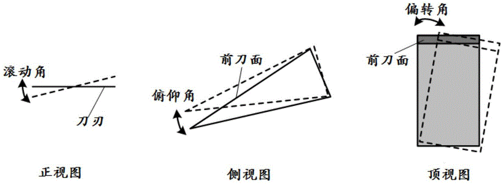
A precision adjustment device for tool rolling angle
A precision adjustment and rolling angle technology, applied in the mechanical field, can solve problems such as the inability to continuously adjust the rolling angle, and achieve the effect of reducing adjustment complexity, reducing assembly errors, and good repeatability
- Summary
- Abstract
- Description
- Claims
- Application Information
AI Technical Summary
Problems solved by technology
Method used
Image

Examples
Embodiment 1
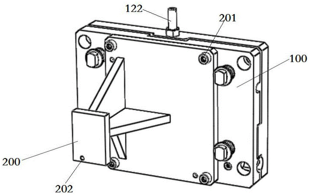
[0039] Such as image 3 As shown, this embodiment provides a precision adjustment device for tool roll angle, including:
[0040] A knife adjustment bracket 100, on which a screw 122 is arranged;
[0041] A cutter mounting frame 200 is fixed on the cutter adjustment bracket 100, and the cutter mounting frame 200 is used to install the cutter head of the cutter;
[0042] Wherein, the rolling angle of the cutter head can be adjusted by rotating the screw rod 122 .
[0043] In a specific implementation process, a plurality of bolts 201 are provided on the tool mounting frame 200 for fixing the tool mounting frame 200 on the tool adjusting bracket 100 .
[0044]In a specific implementation process, a bolt hole 202 is provided on the cutter mounting frame 200 for fixing the cutter head of the cutter by bolts. Here, the cutter head can also be fixed by means of a slot or the like.
[0045] In this embodiment, the roll angle of the cutter head can be continuously adjusted by rotat...
PUM
 Abstract
Description
Claims
Application Information