Preparation method of porous iron oxide nanorod array

A nanorod array and nanoarray technology are applied in the field of precursor iron oxyhydroxide, which can solve the problems of inconspicuous nanorod array structure and increased preparation process.

Inactive Publication Date: 2015-05-20
DALIAN INST OF CHEM PHYSICS CHINESE ACAD OF SCI
View PDF2 Cites 31 Cited by
  • Summary
  • Abstract
  • Description
  • Claims
  • Application Information

AI Technical Summary

Problems solved by technology

[0003] Patent CN102610394A describes a kind of α-Fe 2 The preparation method of O nanorods, however, a buffer layer is add

Method used


Image

  • Preparation method of porous iron oxide nanorod array
  • Preparation method of porous iron oxide nanorod array
  • Preparation method of porous iron oxide nanorod array

Examples


Embodiment 1

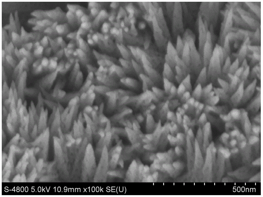
[0026] Soak the Ti plate in acetone, ethanol and deionized water for 30min, then wash it with deionized water, dry it with pure nitrogen, place it in the liner of a hydrothermal kettle, and add 1M NaNO to it. 3 and 0.15M FeCl 3 Mixed solution of water and ethanol, the volume ratio is 7:3; use 0.5M hydrochloric acid solution to adjust the pH value of the solution in the liner to 1, and mix well; seal the hydrothermal kettle and heat it in an oven at 120°C 4h; after the completion of the reaction, the hydrothermal kettle was cooled to room temperature to obtain β-FeOOH; then the conductive glass film sample was calcined at a heating rate of 10°C / min, heated for 1h and then cooled to room temperature to obtain α-FeOOH 2 o 3 nanoarray. figure 1 Shown is the α-Fe prepared in this example 2 o 3 Nanoarray FESEM top view. α-Fe can be seen 2 o 3 It is a porous tapered structure, oriented vertically upwards from the base.

Embodiment 2

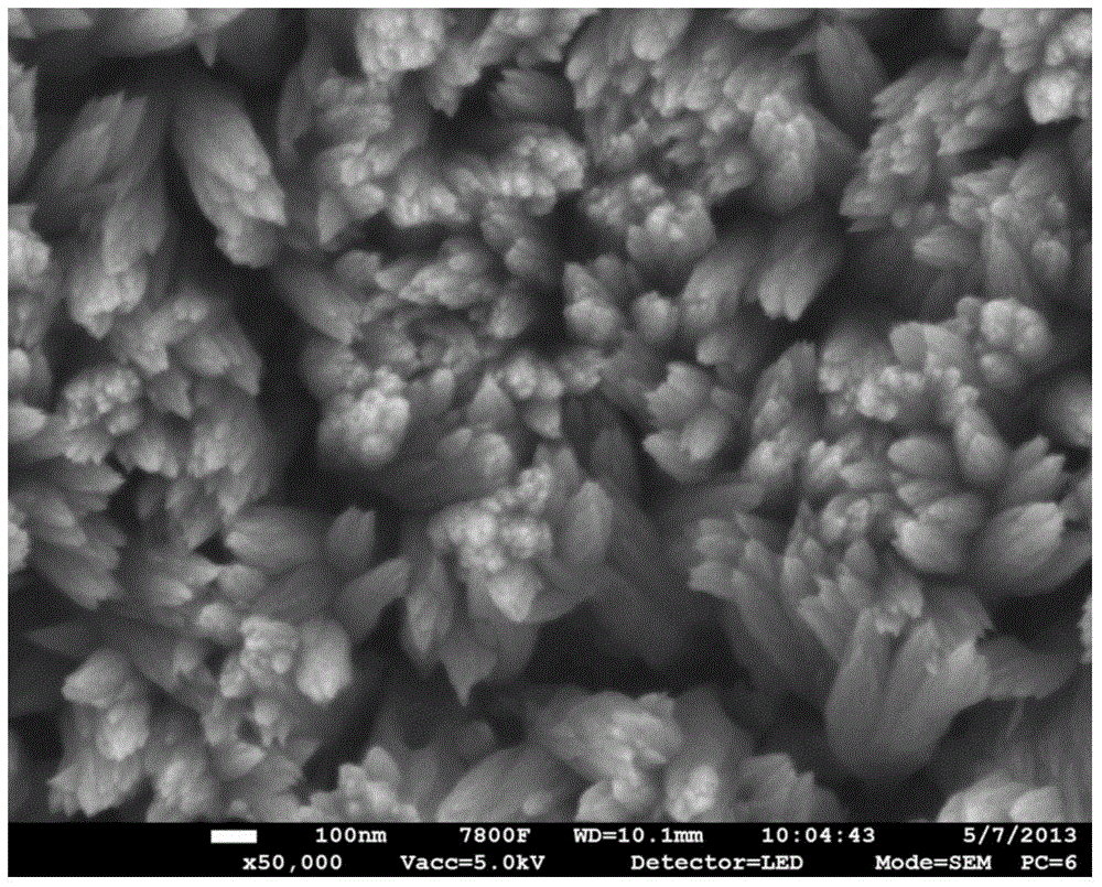
[0028] Put the W plate into acetone, ethanol and deionized water for 30min, soak in ultrasonic for 30min, wash with deionized water, blow dry with pure nitrogen, put it in the liner of a hydrothermal kettle, add 1.5M NaNO 3 and 0.2M FeCl 3 The volume ratio of the mixed solution of water and acetonitrile is 7:5; use 0.5M hydrochloric acid solution to adjust the pH value of the solution in the liner to 1, and mix well; seal the hydrothermal kettle and heat it in an oven at 100°C for 3 hours; After the reaction was completed, the hydrothermal kettle was cooled to room temperature to obtain β-FeOOH; then the conductive glass film sample was calcined at a heating rate of 2°C / min, heated for 2 hours and then cooled to room temperature to obtain α-FeOOH 2 o 3 nanoarray. figure 2 Shown is the porous conical α-Fe prepared in this example 2 o 3 Nanoarray FESEM image.

Embodiment 3

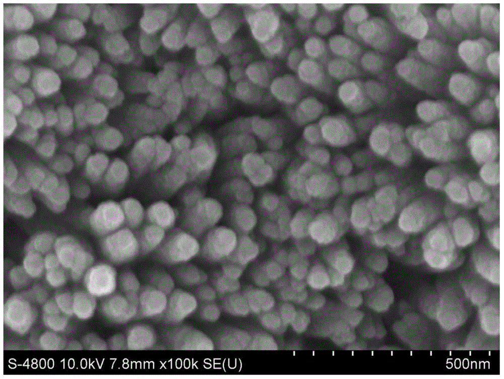
[0030] Soak the Ti plate in acetone, ethanol and deionized water for 30 minutes, then wash it with deionized water, dry it with pure nitrogen, put it in the inner tank of a hydrothermal kettle, and add 0.75M NaNO 3 and 0.075M FeCl 3 The volume ratio of the mixed solution of water and acetonitrile is 7:5; use 0.5M hydrochloric acid solution to adjust the pH value of the solution in the liner to 1, and mix well; seal the hydrothermal kettle and heat it in an oven at 100°C for 4 hours; After the reaction is completed, the hydrothermal kettle is cooled to room temperature to obtain β-FeOOH; then the conductive glass film sample is calcined at a heating rate of 10°C / min, heated for 40 minutes and then cooled to room temperature to obtain porous conical α-FeOOH 2 o 3 nanoarray.

[0031] The resulting porous conical α-Fe 2 o 3 Nanoarray sputtering of Pt metal, it can be seen that the ordered catalyst is evenly distributed on the array. image 3 Shown is the tapered α-Fe prepared...


PUM


Abstract

The invention relates to a preparation method of porous alpha-Fe2O3. The porous alpha-Fe2O3 has a regular and orderly nanorod array structure. The method comprises the following steps: preparing a precursor FeOOH through a hydrothermal synthesis process, and roasting to obtain the porous alpha-Fe2O3 tapered nanorod array structure. The alpha-Fe2O3 prepared through the method is a porous nanorod structure, and nanorods are vertical to a substrate in order to form the regular and orderly array structure. The above material has important application potential in fuel cells and other energy transfer devices as a catalyst carrier, and can also be used in the fields of photoelectrocatalysis and electrochemical catalysis.

Description

technical field [0001] The invention relates to a porous α-Fe 2 o 3 Preparation of nanorod arrays, the precursor iron oxyhydroxide deposited on the surface of the substrate; then calcined at high temperature to obtain conical porous α-Fe 2 o 3 nanorod arrays. This structure has important application potential as catalyst support and photocatalyst. Background technique [0002] As a green functional material, iron oxide is low in cost, rich in resources, biocompatible, environmentally friendly, and has excellent photocatalytic, electrocatalytic and photoelectric conversion properties. It is more and more widely used in biomedicine, pigments, photoelectric Catalytic hydrogen production, photodegradation and electrocatalyst and other fields. α-Fe 2 o 3 Semiconductors have a narrow bandgap so that photoelectric conversion devices can utilize about 40% of the spectral band of sunlight. Synthesis of α-Fe with Controllable Morphology on Substrates by Hydrothermal Synthesis ...

Claims


Application Information

Patent Timeline
IPC IPC(8): C01G49/06B82Y40/00B82Y30/00
Inventor 俞红梅张长昆付丽衣宝廉邵志刚
Owner DALIAN INST OF CHEM PHYSICS CHINESE ACAD OF SCI
Why Eureka
Try Eureka