Fiber manufacturing method and fiber drawing furnace

A manufacturing method and technology of a wire drawing furnace, which can be applied to manufacturing tools, glass manufacturing equipment, etc., can solve the problem of not specifying the type of gas, and achieve the effect of reducing pressure fluctuations

Active Publication Date: 2015-05-20
SUMITOMO ELECTRIC IND LTD
View PDF5 Cites 16 Cited by
  • Summary
  • Abstract
  • Description
  • Claims
  • Application Information

AI Technical Summary

Problems solved by technology

In Patent Document 1, the type of

Method used


Image

  • Fiber manufacturing method and fiber drawing furnace
  • Fiber manufacturing method and fiber drawing furnace
  • Fiber manufacturing method and fiber drawing furnace

Examples


Embodiment Construction

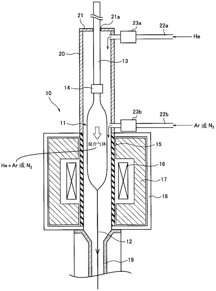
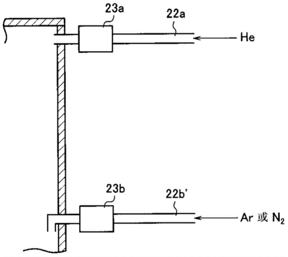
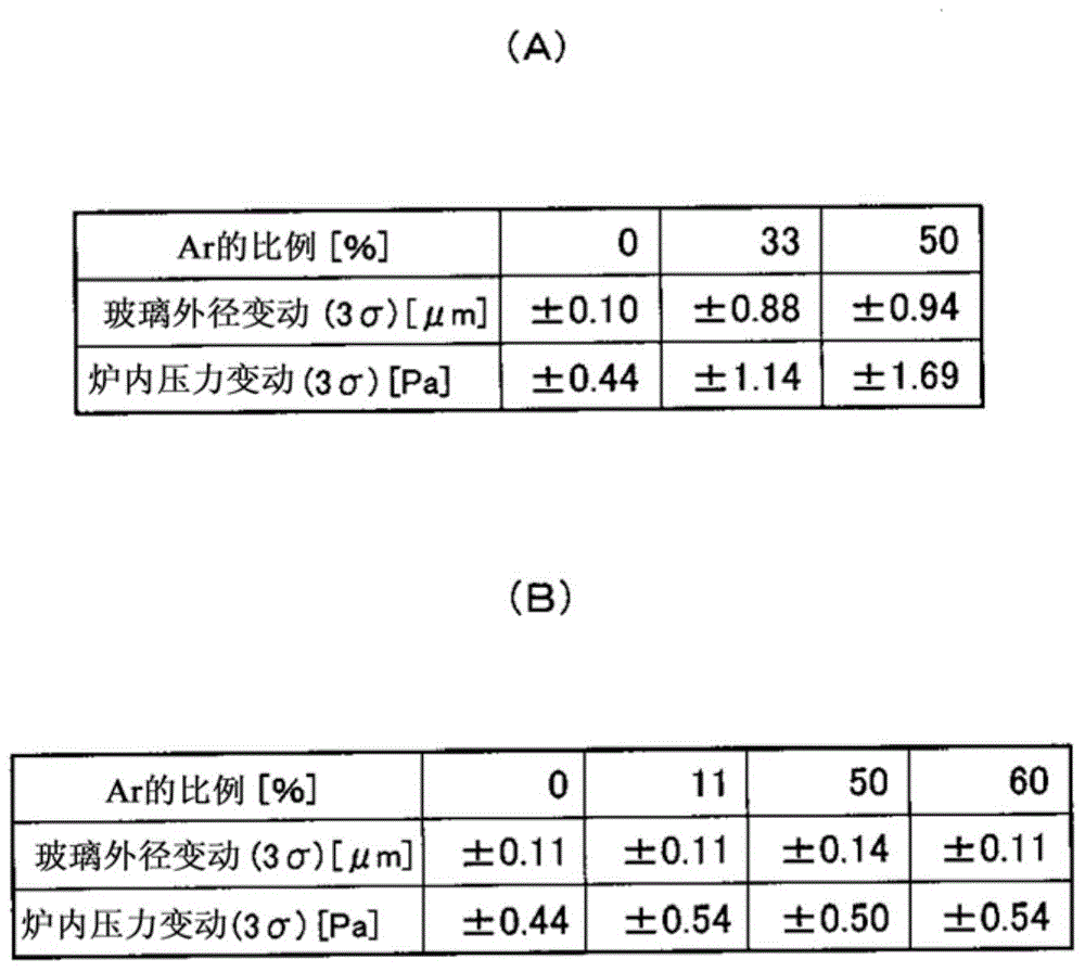
[0016] In the case of using helium gas as an inert gas supplied to the drawing furnace, since this helium gas is expensive and rare, it has been proposed to mix and use a relatively cheap gas such as argon gas. In this case, simply mixing argon and helium will cause pressure fluctuations in the furnace, and the glass diameter of the optical fiber may fluctuate due to the pressure fluctuations.

[0017] The pressure fluctuation in the wire drawing furnace can be considered to occur inside the upper chamber. That is, the upper chamber is disposed above the core tube surrounded by the heater, so the gas heated by the heater rises toward the upper chamber and descends again after being cooled inside the upper chamber. At this time, if argon or nitrogen is used, the density difference (temperature difference) between the gas density in the upper chamber and the gas density in the core tube increases, and it is conceivable that the furnace pressure fluctuation is likely to occur due...


PUM


Abstract

The invention provides a fiber manufacturing method and a fiber drawing furnace, wherein the application amount of the helium gas is reduced and the pressure variation inside the furnace is lowered. Meanwhile, the gas is kept at a certain degree. The fiber drawing furnace (10) comprises a furnace tube (15) used for feeding glass parent material (11); a heater (16) arranged at the periphery of the furnace tube (15); and an upper chamber (20) connected with the upper part of the furnace tube (15) and used for accommodating the glass parent material (11).

Description

technical field [0001] The present invention relates to a method for manufacturing optical fiber by melting and drawing a glass parent material for optical fiber and an optical fiber drawing furnace suitable for the method. Background technique [0002] An optical fiber drawing furnace (hereinafter, also simply referred to as a drawing furnace) is used to melt draw an optical fiber glass base material (hereinafter also simply referred to as a glass base material) mainly composed of silica glass to produce an optical fiber. The optical fiber is manufactured by heating and melting the tip of the glass base material while lowering it from above the drawing furnace into the core tube, and the tip of the glass base material is reduced in diameter and drawn from the bottom of the drawing furnace. At this time, the temperature in the wire drawing furnace is about 2000° C., which is very high, so carbon or the like with good heat resistance is used for parts in the wire drawing furn...

Claims


Application Information

Patent Timeline
IPC IPC(8): C03B37/025C03B37/029
CPCC03B37/025C03B37/029
Inventor 小西达也冈崎岩山崎卓
Owner SUMITOMO ELECTRIC IND LTD
Why Eureka
Try Eureka