Method and device for quick blockage of piping in deep foundation pit

A plugging device and a technology for deep foundation pits, which are used in infrastructure engineering, construction, etc., can solve the problems of low grouting success rate, increase construction costs, damage impermeable layers, etc., and achieve high plugging success rate and safety. and high stability, less time-consuming effect

Inactive Publication Date: 2015-05-20
NO 1 ENG COMPANY CO LTD OF CCCC FIRST HARBOR ENG COMPANY +1
View PDF5 Cites 7 Cited by
  • Summary
  • Abstract
  • Description
  • Claims
  • Application Information

AI Technical Summary

Problems solved by technology

[0005] The technical problem to be solved by the present invention is: when traditionally using rotary grouting piles or mixing piles to block piping, it is necessary to erect relatively complicated operating equipment, which will increase construction costs, and the construction period will be longer, and may In the process, the impermeable layer is further damaged to form a secondary disaster; while the direct grouting is washed away before the grouting liquid solidifies, resulting in a low success rate of grouting

Method used


Image

  • Method and device for quick blockage of piping in deep foundation pit

Examples


Embodiment 1

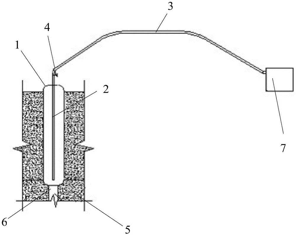
[0023] The present invention provides a method for quick plugging of piping in deep foundation pits, which is mainly used for piping plugging in deep foundation pits in open seas. The height of the bottom surface makes the geotechnical bag 1, and the diameter of the geotechnical bag 1 should be slightly larger than the aperture size of the piping hole 6, so that the piping path can be completely blocked after the geotechnical bag expands; step 2, in the geotechnical bag 1 Insert the grouting pipe 2, the length of the grouting pipe 2 is the same as the height of the geotechnical bag 1, the grouting pipe 2 stretches into the bottom of the geotechnical bag 1, and the geotechnical bag 1 is followed by the grouting pipe 2 Insert the foundation impermeable layer 5 along the piping path, and use the grouting pump 7 to inject the cement slurry into the geotechnical mold bag 1 through the grouting pipe 2; step 3, in the process of injecting cement slurry, the geotechnical mold bag 1 beg...

Embodiment 2

[0027] Compared with Embodiment 1, in step 3 of this embodiment, after stopping the injection of cement slurry into the geotechnical bag 1, the quick-setting agent is injected into the geotechnical bag 1 through the grouting pipe 2, so as to speed up the process in the geotechnical bag 1. The setting speed of cement slurry. Preferably, the quick-setting agent is water glass (sodium silicate). By injecting water glass into the geomembrane bag 1, the solidification of the cement slurry can be accelerated and the construction period can be shortened.

[0028] In the above-mentioned embodiment, the water glass enters the geotechnical bag 1 through the grouting pipe 2. After the water glass enters the geotechnical bag 1, the cement slurry in the geotechnical bag 1 solidifies rapidly, so the grouting pipe 2 There is no way to take it out. At this time, the connecting pipe and the grouting pipe 2 are disconnected, and the grouting pipe 2 is always put into the geotechnical bag 1; Ro...


PUM


Abstract

The invention relates to the technical field of civil engineering, in particular to a method and a device for quick blockage of piping in a deep foundation pit. The method includes: sending geotextile bags to an impervious layer of a foundation through a piping path, grouting cement paste into the geotextile bags through a grouting pump, enabling the geotextile bags to expand to form a plug effect so as to block the piping path, and completing piping blockage after solidification of the cement paste. Compared with a traditional blockage method, the method has the advantages that erection of complex operation equipment is avoided, high blockage success rate, low cost and simplicity and convenience in blockage operation are achieved, the blockage process is low in time consumption, and accordingly construction period can be shortened; in addition, high safety and reliability can be realized after blockage is completed, and piping is less prone to recurrence.

Description

technical field [0001] The invention relates to the technical field of civil engineering, in particular to a method and device for fast sealing of deep foundation pit piping. Background technique [0002] At present, when piping or a large area of ​​leakage occurs in a deep foundation pit, the traditional plugging methods are divided into guiding, dewatering and decompression, water filtering surrounding wells, grouting, water filtering and weighting, and rotary grouting piles or spouting piles depending on the severity of the piping. Stirring pile and so on. However, the above plugging measures have defects to varying degrees. For example, dewatering wells need to be drilled for dewatering and decompression, and complex operating equipment needs to be erected for jet grouting piles and mixing piles. The permeable layer causes secondary disasters; the hidden dangers such as landslides caused by piping cannot be fundamentally eliminated by the use of guiding and filtering su...

Claims


Application Information

Patent Timeline
Patent Type & Authority Applications(China)
IPC IPC(8): E02D19/10
CPCE02D19/16
Inventor 林鸣孟凡利孔令磊张怡戈刘昊槟杨润来孟令月尹海卿刘亚平高纪兵陈三洋冀晋洪志军
Owner NO 1 ENG COMPANY CO LTD OF CCCC FIRST HARBOR ENG COMPANY
Why Eureka
Try Eureka