
A telescopic compensation structure suitable for cryogenic insulation pipes

A low-temperature thermal insulation and compensation structure technology, which is applied to expansion compensation devices, pipe components, pipes/pipe joints/pipe fittings for pipelines, etc., can solve problems such as affecting the effect of vacuuming, difficult expansion and contraction, and inspection of corrugated sections. Achieving the effect of avoiding the intractable dead angle of evacuation, good expansion and compensation ability, and simple structure production

Active Publication Date: 2017-09-22
JEREH OIL & GAS ENG
View PDF8 Cites 0 Cited by
  • Summary
  • Abstract
  • Description
  • Claims
  • Application Information

AI Technical Summary

Problems solved by technology

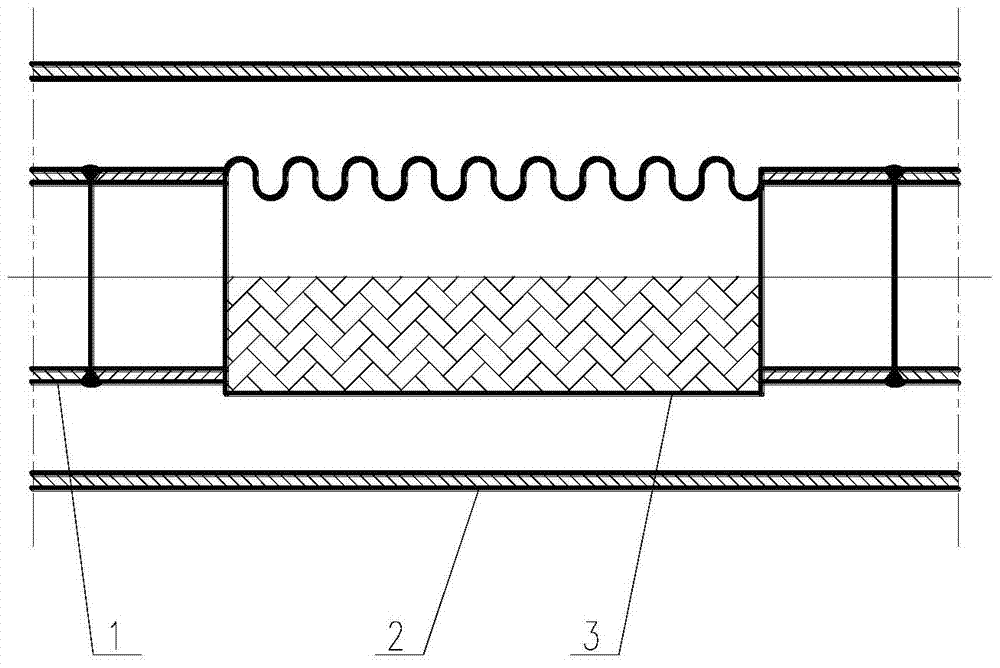
in the attached figure 1 In the metal corrugated hose, because the corrugated net sleeve is added to the outside, although it has played a certain role in improving the rigidity, but at the same time, because both ends have been fixed, it has lost its due compensation function, that is, it is difficult to have sufficient expansion and contraction. In addition, due to the existence of these corrugated mesh sleeves, there is no way to check and clean the grease on the internal corrugated section. When vacuuming the insulation tube, there will be local dead corners that are difficult to evacuate completely, which will affect the vacuuming effect.

Method used


Image

  • A telescopic compensation structure suitable for cryogenic insulation pipes
  • A telescopic compensation structure suitable for cryogenic insulation pipes
  • A telescopic compensation structure suitable for cryogenic insulation pipes

Examples


Embodiment Construction

[0014] The principles and features of the present invention are described below in conjunction with the accompanying drawings, and the examples given are only used to explain the present invention, and are not intended to limit the scope of the present invention.

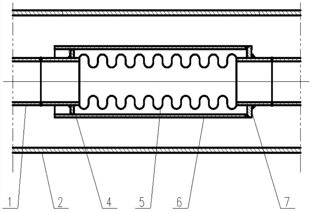
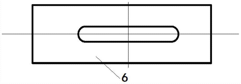
[0015] Such as figure 2 As shown, a telescopic compensation structure suitable for cryogenic insulation pipes includes a protective casing assembly arranged between the inner pipe and the outer pipe of the cryogenic insulation pipe, and the protective casing assembly includes a bellows-shaped expansion joint and a protective sleeve pipe, the expansion joint is arranged inside the protective sleeve, the expansion joint is used to connect two sections of the inner pipe and seal at the joint, the protective sleeve is arranged outside the inner pipe, the Both ends of the protection sleeve are radially provided with an annular support plate and a fixed plate to connect with the inner tube, the support plate is fixedly c...


PUM


Abstract

The invention relates to a telescopic compensation structure suitable for a low-temperature heat insulation tube. The telescopic compensation structure comprises a protecting sleeve tube component arranged between inner tubes and an outer tube of the low-temperature heat insulation tube. The protecting sleeve tube component comprises a corrugated-tube-shaped expansion joint and a protecting sleeve tube. The expansion joint is arranged in the protecting sleeve tube. The expansion joint is used for connecting of the two sections of inner tubes, and sealing is carried out at the connecting portion. The two ends of the protecting sleeve tube are provided with annular supporting plates and fixing plates respectively and are connected with the inner tubes. The supporting plates are fixedly connected with the inner tubes in a spot-welding mode. The fixing plates are fixedly connected with the inner tubes in a full-welding mode. At least two through holes which are distributed in the periphery direction are formed in the tube wall of the protecting sleeve tube. A plurality of evenly-formed through holes are formed in the supporting plates and the fixing plates. Good telescopic compensating capacity is achieved, the basic rigidity using requirements can be met, complete washing can be conveniently carried out on the outer portion of the expanding joint, so that impurities such as grease are removed, and the problem that a dead corner evacuating cannot be solved easily is effectively avoided.

Description

technical field [0001] The invention relates to the fields of long-distance and large-flow transportation of various low-temperature media such as air separation equipment and LNG filling stations, such as liquid oxygen, liquid nitrogen, and liquid argon, and particularly relates to a telescopic compensation structure suitable for low-temperature insulation pipes. Background technique [0002] In order to compensate the thermal expansion and contraction caused by the influence of temperature difference on the cryogenic insulation pipe, expansion and contraction compensation devices are usually installed on the inner or outer pipe. The traditional compensation structure generally uses metal corrugated hoses. in the attached figure 1 In the metal corrugated hose, because the corrugated net sleeve is added to the outside, although it has played a certain role in improving the rigidity, but at the same time, because both ends have been fixed, it has lost its due compensation fun...

Claims


Application Information

Patent Timeline
Patent Type & Authority Patents(China)
IPC IPC(8): F16L51/02
CPCF16L51/025
Inventor 林辉王娜徐强李燕飞
Owner JEREH OIL & GAS ENG
Learn More