Pipeline system flow noise suppression device and method broadening acoustic band gaps

A pipeline system and noise suppression technology, applied in the direction of pipe components, pipes/pipe joints/pipe fittings, mechanical equipment, etc., can solve problems such as performance limitations, achieve simple structure, meet low-frequency broadband noise reduction requirements, and be easy to assemble and apply Effect

Active Publication Date: 2015-05-20
NAT UNIV OF DEFENSE TECH
View PDF6 Cites 7 Cited by
  • Summary
  • Abstract
  • Description
  • Claims
  • Application Information

AI Technical Summary

Problems solved by technology

However, due to its own performance limitations, it has cer

Method used


Image

  • Pipeline system flow noise suppression device and method broadening acoustic band gaps
  • Pipeline system flow noise suppression device and method broadening acoustic band gaps
  • Pipeline system flow noise suppression device and method broadening acoustic band gaps

Examples


Embodiment Construction

[0035] In order to make the present invention clearer, the present invention will be further described below in conjunction with the accompanying drawings.

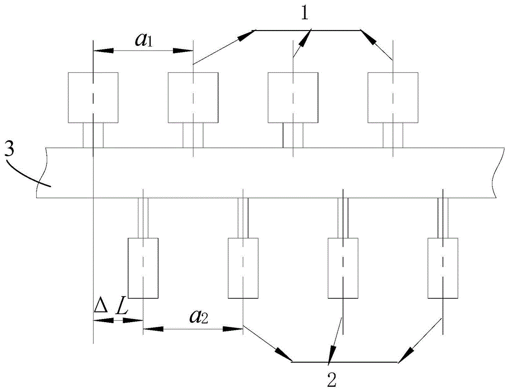
[0036] The invention provides a pipeline system flow noise suppression device for widening the acoustic band gap, the structure of which is as follows: figure 1 As shown, it includes a first muffler 1 , a second muffler 2 and a piping system 3 .

[0037] Wherein, the muffler frequency range of the first muffler 1 is lower than that of the second muffler 2 . The first muffler 1 and the second muffler 2 are placed in the piping system 3 at equidistant intervals, and the placement position of the second muffler 2 has a certain offset ΔL compared with the placement position of the first muffler 1 (such as figure 1 shown).

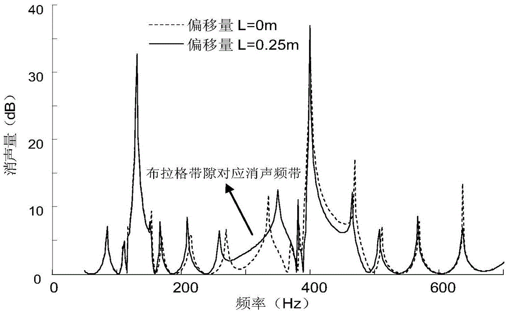
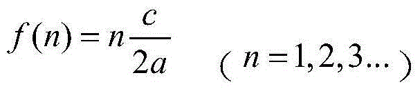
[0038] The anechoic frequency band of the first muffler 1 should be below the initial frequency of its target band gap. According to the Bragg band gap mechanism, it will form a Bragg acoustic band gap t...


PUM


Abstract

The invention discloses pipeline system flow noise suppression device and method broadening acoustic band gaps. The device comprises a pipeline system, first mufflers and second mufflers, wherein the first mufflers and the second mufflers are respectively arranged in the pipeline system in cycles, and the muffling frequency range of the first mufflers is smaller than that of the second mufflers. According to the pipeline system flow noise suppression device and method broadening the acoustic band gaps, the in-pipe flow noise transmission is suppressed by the adoption of Prague band gaps and local resonance band gaps generated by a cellular photonic crystal pipeline with the composition of the first mufflers and the second mufflers; certain offsets are taken during the arrangement of the two kinds of mufflers, so that the Prague band gaps can be further broadened, and the suppression of low frequency broadband flow noise in the pipeline is achieved.

Description

technical field [0001] The invention relates to the field of vibration and noise control, in particular to a pipeline system flow noise suppression device and method for widening the acoustic band gap. Background technique [0002] During the working process of the pipeline system, flow noise will be generated in the pipeline and spread to the outside through the pipeline outlet. The sound pressure level of this kind of flow noise is generally higher than the noise radiated directly to the outside by the vibration of the pipeline, which is more harmful. For example, the pipes of power plants and chemical plants radiate noise outward, affecting the normal life and work of people around them. Flow noise radiated outward from some combat platforms is easily detected by enemy sonar. In addition, strong noise will cause the structure to break due to fatigue and cause accidents. Therefore, it is of great significance to eliminate flow noise. [0003] At present, there are main...

Claims


Application Information

Patent Timeline
IPC IPC(8): F16L55/033
CPCF16L55/033
Inventor 温激鸿郁殿龙张亚峰沈惠杰温熙森
Owner NAT UNIV OF DEFENSE TECH
Why Eureka
Try Eureka