Auxiliary fire device for gas burner

A gas burner and sub-fire technology, applied in the direction of burner safety devices, gas fuel burners, burners, etc., can solve the problems of high ignition failure rate, short service life, poor safety performance, etc., to avoid misoperation, Long service life, monitoring and stable effect

Active Publication Date: 2015-05-20
王彦
View PDF9 Cites 0 Cited by
  • Summary
  • Abstract
  • Description
  • Claims
  • Application Information

AI Technical Summary

Problems solved by technology

[0010] The purpose of the present invention is to provide a sub-ignition device for gas burners to solve the existing technologies of complex structure, large volume, high ignition failure rate, poor safety performance, short service life and high investment cost in the prior art. question

Method used


Image

  • Auxiliary fire device for gas burner
  • Auxiliary fire device for gas burner
  • Auxiliary fire device for gas burner

Examples


Embodiment 1

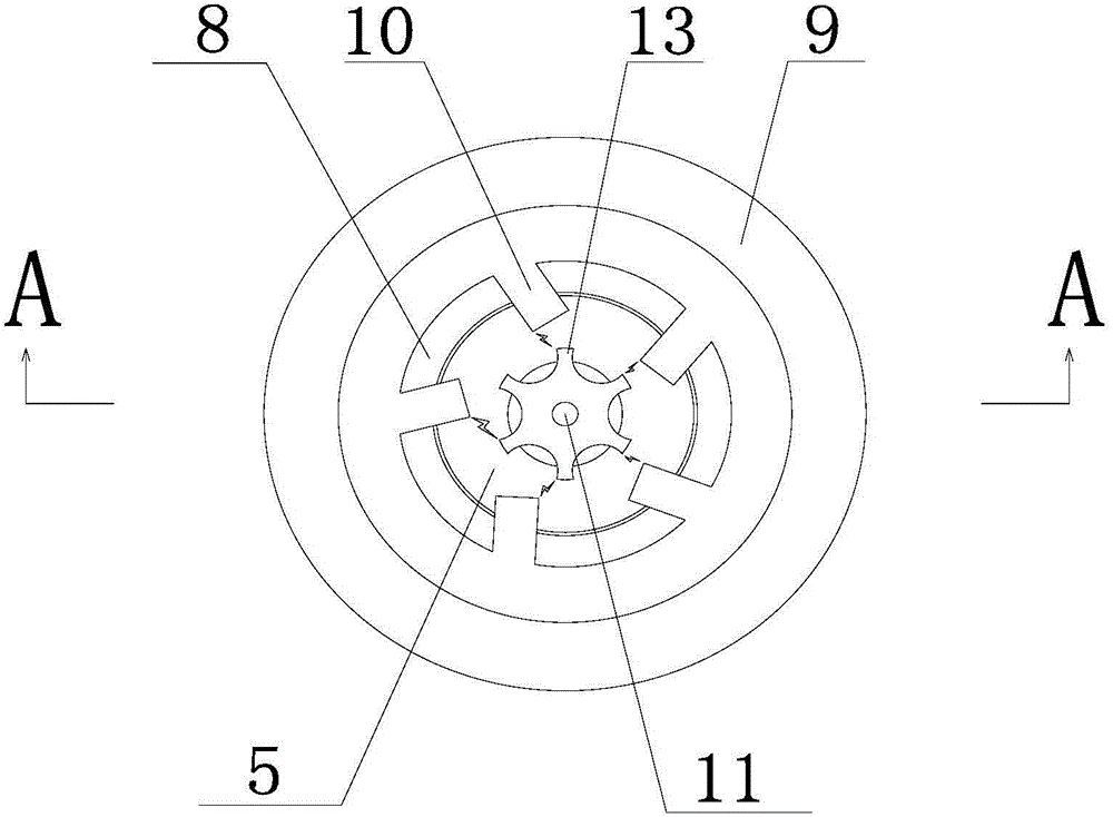
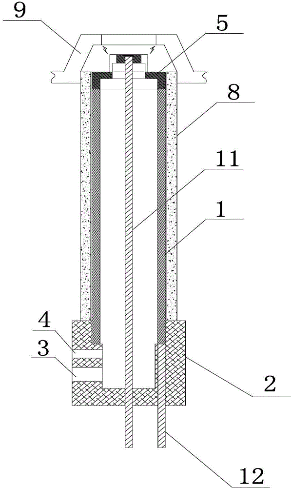
[0046] figure 1 A top view of a sub-ignition device for a gas burner provided in an embodiment of the present invention; figure 2 for figure 1 Middle A-A sectional view; image 3 A partial enlarged view of a secondary fire device for a gas burner provided in an embodiment of the present invention; Figure 1-3 As shown, a sub-ignition device for a gas burner provided in this embodiment includes a metal pipe 1, one end of the metal pipe 1 is connected with an insulating base 2, the insulating base 2 seals the metal pipe 1, and the insulating base 2 is respectively provided with a The air inlet 3 and the gas inlet 4 connected by the metal pipe 1;

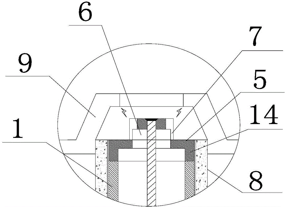
[0047] The end of the metal pipe 1 away from the insulating base 2 is provided with a cover 5, and the cover 5 is provided with a protrusion extending upward, and the protrusion is provided with a blind hole 6, the bottom of which is connected to the metal pipe, and the bottom of the blind hole 6 is connected to the metal pipe. Th...

Embodiment 2

[0055] figure 1 A top view of a sub-ignition device for a gas burner provided in an embodiment of the present invention; figure 2 for figure 1 Middle A-A sectional view; image 3 A partial enlarged view of a secondary fire device for a gas burner provided in an embodiment of the present invention; Figure 1-3 As shown, a sub-ignition device for a gas burner provided in this embodiment includes a metal pipe 1, one end of the metal pipe 1 is connected with an insulating base 2, the insulating base 2 seals the metal pipe 1, and the insulating base 2 is respectively provided with a The air inlet 3 and the gas inlet 4 connected by the metal pipe 1;

[0056] The end of the metal pipe 1 away from the insulating base 2 is provided with a cover 5, and the cover 5 is provided with a protrusion extending upward, and the protrusion is provided with a blind hole 6, the bottom of which is connected to the metal pipe, and the bottom of the blind hole 6 is connected to the metal pipe. Th...


PUM


Abstract

The invention provides an auxiliary fire device for a gas burner. An insulating base is connected to one end of a metal pipe, and a projection with a blind hole is arranged on a seal cover which is arranged at one end, close to the insulating base, of the metal pipe. The side wall of the projection is provided with a hybrid gas outlet. The auxiliary fire device for the gas burner has the advantages that the seal cover, the projection and a metal wire form a thermocouple, and the metal wire and a fusion point between the metal wire and a top cover cannot be directly burned by flames, so that service life of the thermocouple is prolonged; in addition, the metal wire, the seal cover, the projection and the fusion point between the metal wire and the top cover can be constantly and completely cooled by air flow, generation of temperature difference potential is benefited to realize amplification of monitoring sensible capacity, high stability and reliability in monitoring are achieved, and misoperation can be avoided.

Description

technical field [0001] The invention relates to the technical field of gas burner equipment, in particular to a sub-fire device for a commercial blower type gas burner with a flameout protection device. Background technique [0002] The burner is a thermal energy device that sends fuel and air into the furnace according to the required concentration, speed, turbulence and mixing method, and enables the fuel to ignite and burn stably in the furnace. [0003] At present, the ignition part of a commonly used commercial blast burner includes a sub-ignition device and a flameout protection device. Among them, the sub-ignition device is used to provide the fire source, and the flameout protection device is used to cut off the gas source in the case of accidental flameout. When in use, the sub-fire device (blast type) is ignited, and the main fire burner is ignited through its fire source. The flameout protection device includes a thermocouple, which monitors the continuity of the...

Claims


Application Information

Patent Timeline
Patent Type & Authority Applications(China)
IPC IPC(8): F23D14/02F23D14/46
CPCF23D14/02F23D14/46F23D14/725F23D2209/00
Inventor 王彦
Owner 王彦
Why Eureka
Try Eureka