Eureka AIR delivers breakthrough ideas for toughest innovation challenges, trusted by R&D personnel around the world.

Furnace

A furnace hearth and furnace body technology, which is used in household furnaces/stoves, lighting and heating equipment, solid heating fuels, etc., can solve problems such as energy waste, high labor intensity, and clogging of ash leakage holes, and achieve pollution-free operation and ash cleaning. thorough effect

Inactive Publication Date: 2015-05-20
XUZHOU JIAGU ENVIRONMENTAL PROTECTION TECH
View PDF0 Cites 6 Cited by
  • Summary
  • Abstract
  • Description
  • Claims
  • Application Information

AI Technical Summary

Problems solved by technology

However, most of the furnaces do not meet the above requirements at present. Since the size of the ash leakage hole on the grate in the furnace has been fixed during production, it is difficult to apply the furnace when the size of the fuel (such as coal) is changed, that is, the ash leakage If the hole is large, the fuel may fall before it is fully burned. If the ash leak hole is small, it is difficult to ensure that the burned fuel will fall smoothly, which will block the ash leak hole and cause poor ventilation in the furnace to affect fuel combustion. Personnel can only open the furnace door and use steel brazing to clean the dust on the furnace grate, resulting in heavy pollution and high labor intensity. In addition, there may be a large amount of unburned fuel in the furnace, which will also be cleaned up, resulting in a large waste of energy.

Method used


Image

  • Furnace
  • Furnace

Examples


Embodiment Construction

[0016] The present invention will be further described below in conjunction with drawings and embodiments.

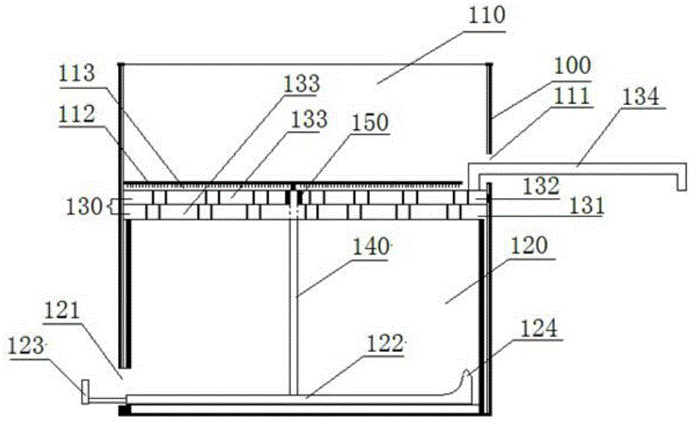
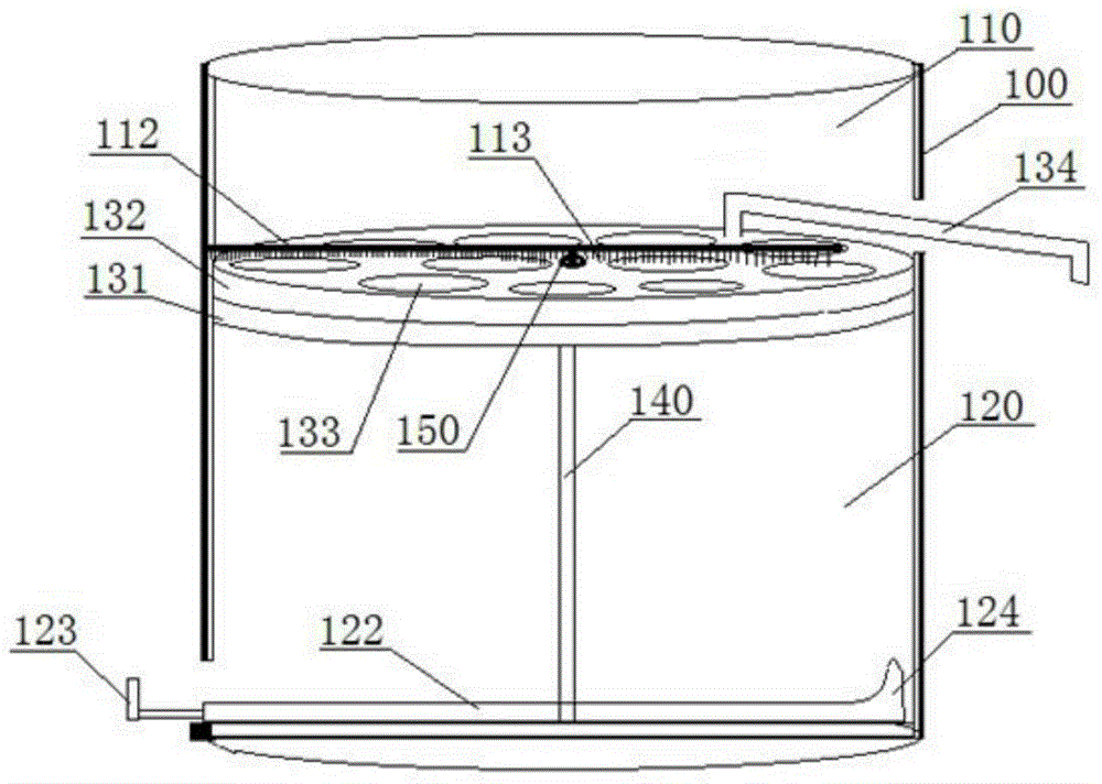
[0017] like figure 1 , 2 , a furnace, including a furnace body 100, the furnace body 100 includes a combustion cavity 110 and a ventilation cavity 120, the combustion cavity 110 and the ventilation cavity 120 are separated by a grate plate 130, and the grate plate 130 includes Relying on the fixed grate plate 131 and the rotating grate plate 132, the fixed grate plate 131 is fixedly installed in the furnace body 100, the rotating grate plate 132 is installed above the fixed grate plate 131, and the middle part of the furnace body 100 is vertically provided with a support rod 140, The lower part of the support rod 140 is fixed on the bottom of the furnace body 100, and the upper part passes through the center of the fixed grate plate 131 and the rotating grate plate 132 in turn, the fixed grate plate 131 is fixedly connected with the support rod 140, and the rotating gr...


PUM


Abstract

The invention discloses a furnace which comprises a furnace body. The furnace body comprises a combustion cavity and a ventilation cavity. The combustion cavity and the ventilation cavity are separated by a grate plate. The grate plate comprises a fixed grate plate body and a rotary grate plate body which are attached to each other. The fixed grate plate body is fixedly installed in the furnace body. The rotary grate plate body is installed on the upper portion of the fixed grate plate body. The main body of the rotary grate plate body and the main body of the fixed grate plate body are each provided with a plurality of through holes. The overlapped portions of the through holes in the fixed grate plate body and the through holes in the rotary grate plate body form grate plate through holes. The size of the grate plate through holes can be adjusted by rotating the rotary grate plate body. Compared with the prior art, due to the fact that the grate plate is divided into the fixed grate plate body and the rotary grate plate body which are attached to each other, the grate plate through holes in the grate plate can be adjusted according to the size of combusting fuel, it is ensured that the fuel can be sufficiently combusted in the furnace, completely-combusted fuel ash can be rapidly removed in time, no pollution is produced in the ash removing process, and operation is easy and convenient.

Description

technical field [0001] The invention relates to a furnace, belonging to the technical field of furnaces. Background technique [0002] The furnace is a three-dimensional space surrounded by furnace walls for fuel combustion. The function of the furnace is to ensure that the fuel is burned as much as possible, and to cool the temperature of the flue gas at the outlet of the furnace to the temperature allowed for the safe operation of the convection heating surface. However, most of the furnaces do not meet the above requirements at present. Since the size of the ash leakage hole on the grate in the furnace has been fixed during production, it is difficult to apply the furnace when the size of the fuel (such as coal) is changed, that is, the ash leakage If the hole is large, the fuel may fall before it is fully burned. If the ash leak hole is small, it is difficult to ensure that the burned fuel will fall smoothly, which will block the ash leak hole and cause poor ventilation...

Claims


Application Information

Patent Timeline
Patent Type & Authority Applications(China)
IPC IPC(8): F24B1/197F24B1/193
Inventor 宋忠红宋佳楠王春华
Owner XUZHOU JIAGU ENVIRONMENTAL PROTECTION TECH
Why Eureka
Eureka Blog
Learn More