Flow chamber of flow cytometer

A flow cytometer and flow chamber technology, applied in the field of flow chambers, can solve the problems of increased signal changes, decreased data quality, and decreased detection accuracy of cytometers, achieving the effects of improved detection accuracy, high detection accuracy, and reduced diameter

Inactive Publication Date: 2015-05-20
CHANGCHUN INST OF OPTICS FINE MECHANICS & PHYSICS CHINESE ACAD OF SCI
View PDF5 Cites 2 Cited by
  • Summary
  • Abstract
  • Description
  • Claims
  • Application Information

AI Technical Summary

Problems solved by technology

[0003] In order to solve the problem of sample flow existing in the flow cell of the existing flow cytometer, when the sampling rate is increased, the cells or particles to be tested deviate from the center of the irradiation spot, which makes the irradiation energy uneven, resulting in increased signal changes and decreased data quality, thus causing cells to In order to solve the problem of decreased detection accuracy of the instrument, the invention provides a flow chamber of a flow cytometer

Method used


Image

  • Flow chamber of flow cytometer

Examples


Embodiment Construction

[0023] The present invention will be described in further detail below in conjunction with the accompanying drawings.

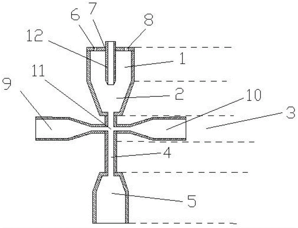
[0024] Such as figure 1 As shown, the flow chamber of a flow cytometer of the present invention is composed of an inlet area 1, a convergence area 2, an adjustment area 3, a detection area 4 and an auxiliary area 5, and the inlet area 1, the convergence area 2, the adjustment area 3, the detection area The zone 4 and the auxiliary zone 5 are closely connected in turn to form a whole. The upper end of the inlet area 1 is provided with a main sheath liquid inlet 6, a sample inflow port 7 and an air pressure adjustment port 8, the sample inflow port 7 is located between the main sheath liquid inlet 6 and the air pressure adjustment port 8, and the sample inflow port 7 is used to place the sample flow tube 12. The sample flow tube 12 enters the inlet area 1 along the sample inflow port 7 and reaches the converging area 2. The air pressure adjustment port 8 is us...


PUM

PropertyMeasurementUnit
diameteraaaaaaaaaa

Abstract

The invention discloses a flow chamber of a flow cytometer, and relates to the field of flow cytometers. By adopting the flow chamber, the problems that when the sample feeding rate of a sample flow of an existing flow cytometer is increased, to-be-tested cells or micro-particles are deviated from the central position of an irradiation light spot to cause that the irradiation energy is non-uniform, signal changes are increased, and data quality is reduced, and thus the detection precision of the cytometer is reduced can be solved. The flow chamber comprises an inlet area, a converging area, an adjusting area, a detection area and an auxiliary area, wherein the inlet area is provided with a main sheath liquid inlet, a sample flow inlet and an air pressure adjusting opening, the adjusting area is provided with two adjusting area inlets and a comprehensive adjusting area, main sheath liquid enters the inlet area from the sheath liquid inlet, the sample flow enters the converging area from a sample flow pipe, and the main sheath liquid and the sample flow are converged into a steady laminar flow in the converging area by using hydrodynamic focusing characteristics and then sequentially enter the comprehensive adjusting area, the detection area and the auxiliary area. According to the flow chamber disclosed by the invention, relatively high detection precision can be achieved at both high and low sample flow sample feeding rates, particularly, the nuclear flow diameter obtained after the sample flow is converged can be reduced at a high sample flow sample feeding rate, and high precision can be achieved.

Description

technical field [0001] The invention relates to the technical field of flow cytometer, in particular to a flow chamber of the flow cytometer. Background technique [0002] Flow cytometry can perform multi-parameter, quantitative analysis or sorting of cells or biological particles in a fast-flowing state. It has been widely used in basic research such as cell biology, immunology, physiology, and molecular biology. It is used in medical clinical diagnosis, environmental detection and so on. As one of the key components of the flow cytometer, the main function of the flow chamber is to arrange the cells or other particles in the sample suspension in a single row and pass through the laser detection area sequentially and orderly. The flow chamber uses the principle of hydrodynamic focusing to converge the sheath fluid and the sample flow in the flow chamber, so that the sample flow forms a stable laminar flow, commonly known as nuclear flow. At this time, the sheath fluid surr...

Claims


Application Information

Patent Timeline
Patent Type & Authority Applications(China)
IPC IPC(8): G01N15/14
Inventor 高庆嘉孙强赵建
Owner CHANGCHUN INST OF OPTICS FINE MECHANICS & PHYSICS CHINESE ACAD OF SCI
Why Eureka
Try Eureka