Data transmission method, base station and user equipment

A technology for transmitting data and base stations, which is applied in the field of communications and can solve problems such as the inability of user equipment and base stations to transmit data, the inability of base stations to send scheduling signaling and feedback normally, and the inability of user equipment to perform normal feedback.

Inactive Publication Date: 2015-05-20
HUAWEI TECH CO LTD
View PDF5 Cites 19 Cited by
  • Summary
  • Abstract
  • Description
  • Claims
  • Application Information

AI Technical Summary

Problems solved by technology

[0004] However, with the advancement of technology, special subframes are introduced in the LTE system. These special subframes may be in the uplink or downlink, and these special subframes can only be used for some special services, such as multimedia broadcasting Multicast service (Multimedia Broadcast Multicast Service, referred to as "MBMS"), device to device (Device to Device, referred to as "D2D") service or machine type communication (Machine Type Communication, referred to as "MTC") service, etc., these Special subframes cannot be used for data transmission in ordinary services other than the above-mentioned special services, nor can they be used for these data scheduling and feedback
In this way, due to the existence of special subframes, the base station may not be able to send scheduling signaling and feedback normally, or the user equipment may not be able to perform normal feedback, which affects the normal data transmission between the user equipment and the base station
The main purpose of the present invention is to solve the problem that normal data transmission cannot be performed between the user equipment and the base station due to the existence of special subframes

Method used


Image

  • Data transmission method, base station and user equipment
  • Data transmission method, base station and user equipment
  • Data transmission method, base station and user equipment

Examples


Embodiment Construction

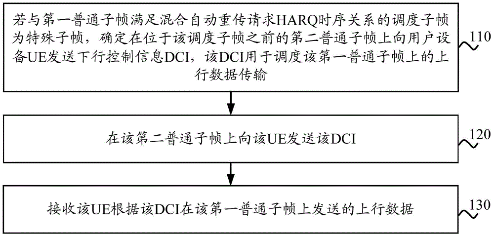
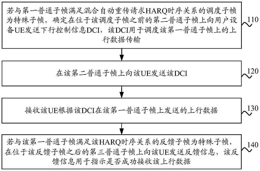
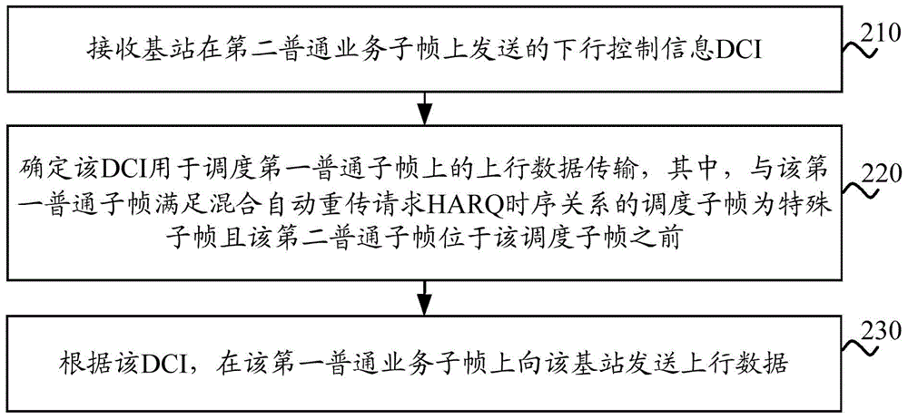
[0140] The following will clearly and completely describe the technical solutions in the embodiments of the present invention with reference to the drawings in the embodiments of the present invention. Obviously, the described embodiments are part of the embodiments of the present invention, not all of them. Based on the embodiments of the present invention, all other embodiments obtained by persons of ordinary skill in the art without making creative efforts shall fall within the protection scope of the present invention.

[0141] It should be understood that the technical solutions of the embodiments of the present invention can be applied to various communication systems, for example: Global System of Mobile communication (Global System of Mobile communication, referred to as "GSM") system, Code Division Multiple Access (Code Division Multiple Access, referred to as "CDMA") system, Wideband Code Division Multiple Access (referred to as "WCDMA") system, General Packet Radio S...


PUM


Abstract

A data transmission method, a base station and user equipment are disclosed in the present invention. The method comprises: if a scheduling sub-frame satisfying a Hybrid Automatic Repeat reQuest (HARQ) timing relationship with a first common sub-frame is a special sub-frame, then determining to send Downlink Control Information (DCI) to User Equipment (UE) in a second common sub-frame before the scheduling sub-frame, wherein the DCI is used for scheduling uplink data transmission in the first common sub-frame; sending the DCI to the UE in the second common sub-frame; and receiving the uplink data that the UE sends in the first common sub-frame on the basis of the DCI. In accordance with the data transmission method in an embodiment of the present invention, the base station performs scheduling of and feedback to the UE in the common sub-frame in the case that the special sub-frame exists, so that the problem that normal data transmission can not be performed between the UE and the base station due to the existence of the special sub-frame can be solved, thus improving system performance and user experience.

Description

technical field [0001] The embodiments of the present invention relate to the communication field, and more specifically, to a method for transmitting data, a base station, and user equipment. Background technique [0002] In the Long Term Evolution (referred to as "LTE") system, when the base station needs to schedule a certain user equipment, it will send a message to the user equipment (User Equipment, referred to as "UE") on the downlink. Downlink Control Information (Downlink Control Information, "DCI" for short), the DCI may schedule the UE to perform data transmission on the uplink, and may also schedule the UE to perform data reception on the downlink. For uplink scheduling, if the UE receives DCI sent by the base station on subframe n and the DCI is used to schedule uplink transmission, the UE will send uplink data to the base station on subframe n+k. Frame n+k and subframe n satisfy the hybrid automatic repeat request (Hybrid Automatic Repeat reQuest, referred to ...

Claims


Application Information

Patent Timeline
IPC IPC(8): H04W72/04H04L1/00H04L1/16H04L1/18
CPCH04L1/0027H04L1/16H04L1/1806H04W72/0446H04W88/08H04W72/21H04L1/1854H04L5/0053
Inventor 李强大卫·马瑞泽
Owner HUAWEI TECH CO LTD
Why Eureka
Try Eureka