
Node structures for lattice frames

A node structure and frame technology, applied in underwater structures, infrastructure engineering, building construction, etc., can solve the problems of unrealistic bottom structures, achieve weight and cost reduction, compact node structure, and reduce thickness Effect

Inactive Publication Date: 2015-05-20
MHI VESTAS OFFSHORE WIND AS
View PDF4 Cites 3 Cited by
  • Summary
  • Abstract
  • Description
  • Claims
  • Application Information

AI Technical Summary

Problems solved by technology

Jackets have been used in the oil and gas industry for many years; more recently they have also gained favor in offshore wind turbine applications where water depths in excess of about twenty meters Gravity's bottom structure is impractical

Method used


Image

  • Node structures for lattice frames
  • Node structures for lattice frames
  • Node structures for lattice frames

Examples


Embodiment Construction

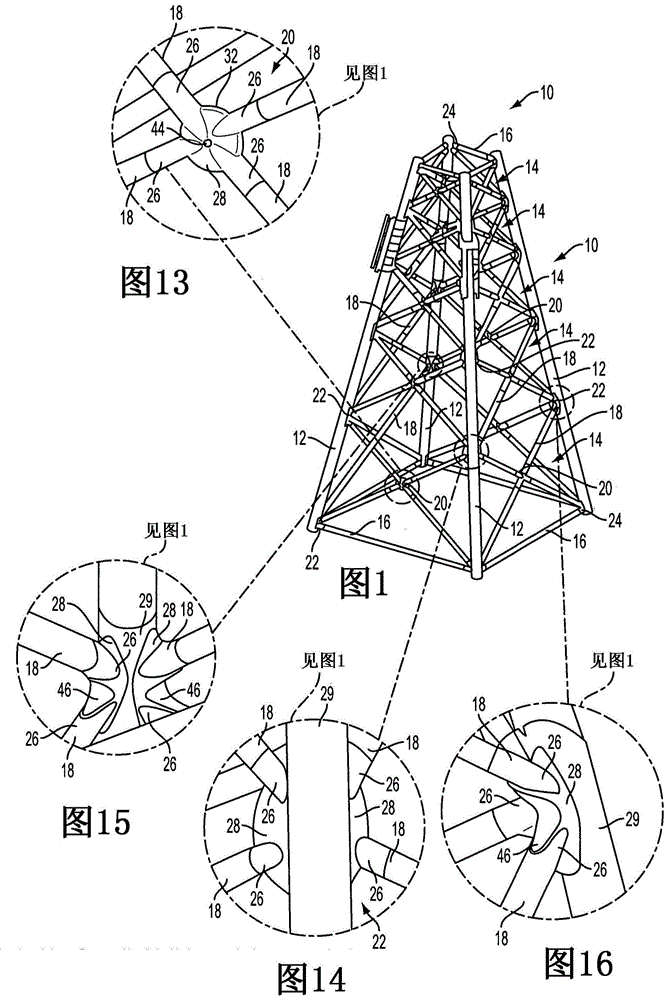
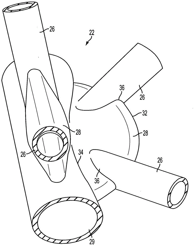
[0038] referenced figure 1 The invention is put in context. Then, next refer to the attached Figure 2 to Figure 6 , these figures show a double K-shaped node structure 22, which is used to figure 1 One member of the lattice frame jacket 10 shown in FIG. 10 (ie, the tubular leg 12 ) is connected to four other members of the jacket 10 (ie, the four tubular diagonal struts 18 ). The diagonal struts 18 are grouped in two pairs in mutually orthogonal planes about the central longitudinal axis of the leg 12 .

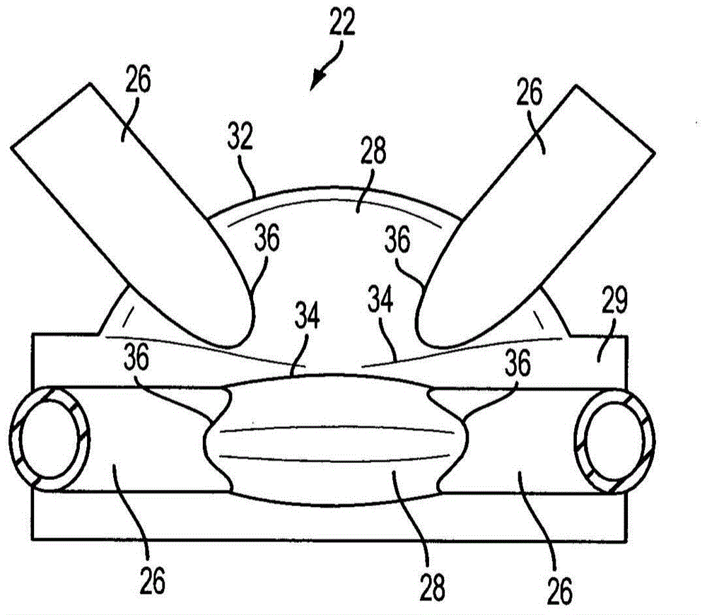
[0039] Each pair of diagonal struts 18 converges on a double K-shaped node structure 22 where each pair of diagonal struts is aligned and connected to a corresponding root 26 that converges at a corresponding hollow brace 28 and welded to the bracket. Each bracket 28 is welded to a leg 29 aligned with and connected to the other segments of leg 12 .

[0040] as in Figure 5 As best shown in , each bracket 28 includes opposing dish-shaped walls 30 that converge in cross-...


PUM


Abstract

A node structure for connecting a member of a lattice frame to one or more other members of the frame comprises a hollow brace having opposed walls that converge outwardly at an acute angle in cross-section toward a central plane to connect at an outer edge. At least one root portion has a central longitudinal axis extending outwardly in the central plane of the brace for alignment with a member of the frame. The root portion has an inner end cut away at opposite sides around the central plane to leave a joining surface that intersects the converging walls of the brace while embracing an outer region of the brace extending inwardly from the outer edge.

Description

technical field [0001] The invention relates to a node structure of a lattice frame and a method for assembling the node structure. Background technique [0002] A lattice frame comprises elongate members, usually tubes, lying on intersecting longitudinal axes and which may be joined by node structures where those axes intersect. Such node structures may be cast in one piece, or may be welded from multiple parts. [0003] An example of a lattice frame is the "jacket" substructure of a wind turbine or other offshore structure, which will be used in the following description to illustrate the invention. Jackets have been used in the oil and gas industry for many years; more recently they have also gained favor in offshore wind turbine applications where water depths in excess of about twenty meters Gravity's bottom structure is impractical. [0004] figure 1 A jacket for an offshore wind turbine is shown in . figure 1 The jacket 10 shown in is of a conventional general sh...

Claims


Application Information

Patent Timeline
Patent Type & Authority Applications(China)
IPC IPC(8): E04B1/19E04H12/08E04H12/10E02B17/00E04B1/58
CPCE02B17/0004E02B17/027E04B1/1903E04B1/585E04H12/10E04H12/085F05B2240/9121F03D13/20Y02E10/72Y02E10/728Y10T29/49627Y10T403/34B21D47/00
Inventor G·拉尔森N·C·奥尔森
Owner MHI VESTAS OFFSHORE WIND AS
Learn More